Image forming apparatus and image forming method

a technology of image forming apparatus and fuser, which is applied in the direction of electrographic process apparatus, instruments, developers, etc., can solve the problems of insufficient transfer, and achieve the effect of facilitating the adhesion of thin paper to the fuser and easy causing insufficient transfer

Active Publication Date: 2019-02-28
CANON KK
View PDF0 Cites 1 Cited by
  • Summary
  • Abstract
  • Description
  • Claims
  • Application Information

AI Technical Summary

Benefits of technology

[0007]Accordingly, the present disclosure provides an image forming apparatus and an image forming method that do not easily allow thin paper to stick to the fuser even during fixing at low temperature and do not easily cause insufficient transfer (nonuniform transfer) even when repeatedly used in a high-temperature, high-humidity environment.

Problems solved by technology

Accordingly, the present disclosure provides an image forming apparatus and an image forming method that do not easily allow thin paper to stick to the fuser even during fixing at low temperature and do not easily cause insufficient transfer (nonuniform transfer) even when repeatedly used in a high-temperature, high-humidity environment.

Method used


Image

  • Image forming apparatus and image forming method
  • Image forming apparatus and image forming method
  • Image forming apparatus and image forming method

Examples


examples

[0286]The subject matter of the present disclosure will be further described in detail with reference to the following Production Examples, Examples, and Comparative Examples. In the following description, “part(s)” is on a mass basis unless otherwise specified.

Production of Intermediate Transfer Belt

Belt 8-1

Base Layer Formation:

[0287]A base layer 8b of belt 8-1 was formed as described below.

[0288]A poly(ethylene naphthalate) resin (PEN) in which carbon black is dispersed as an electric resistance adjusting agent was formed into a bolt form by stretch blow molding, and the bolt form was cut into an endless belt with an ultrasonic cutter. The resulting 70 μm-thick PEN resin belt was used as the base layer 8b of belt 8-1.

Preparation of Surface Layer Forming Coating Liquid (UV-Curable Resin Composition):

[0289]The coating liquid used for forming the surface layer 8a of belt 8-1 was prepared as described below.

[0290]In a container shielded from UV light, the following ingredients were mi...

examples 1 to 17

, Comparative Examples 1 to 11

[0354]The intermediate transfer belts shown in Table 1 and the toners shown in Tables 2 and 3 were examined in terms of sticking during fixing at low temperature, nonuniform transfer, and low-temperature fixability. The results are shown in Table 4.

[0355]Table 4 suggests that Examples 1 to 17 do not easily allow thin paper to stick to the fuser during fixing at low temperature and do not cause nonuniform transfer even after repetitive use in a high-temperature, high-humidity environment. Although Examples 1 to 17 shown in Table 4 used either belt 8-1 or 8-2 for convenience sake, the toners used in Examples 1 to 17 produced excellent results to the same extent even when used in combination with either of the belts.

TABLE 2Conditions for preparation oforganosilicon compound solutionAddition of organosiliconTemperatureTimecompound solutionOrganosilicon compoundpH(° C.)(min.)(parts by mass)Toner 1Methyltriethoxysilane1.560220.0Toner 2Methyltriethoxysilane1.5...


PUM


Abstract

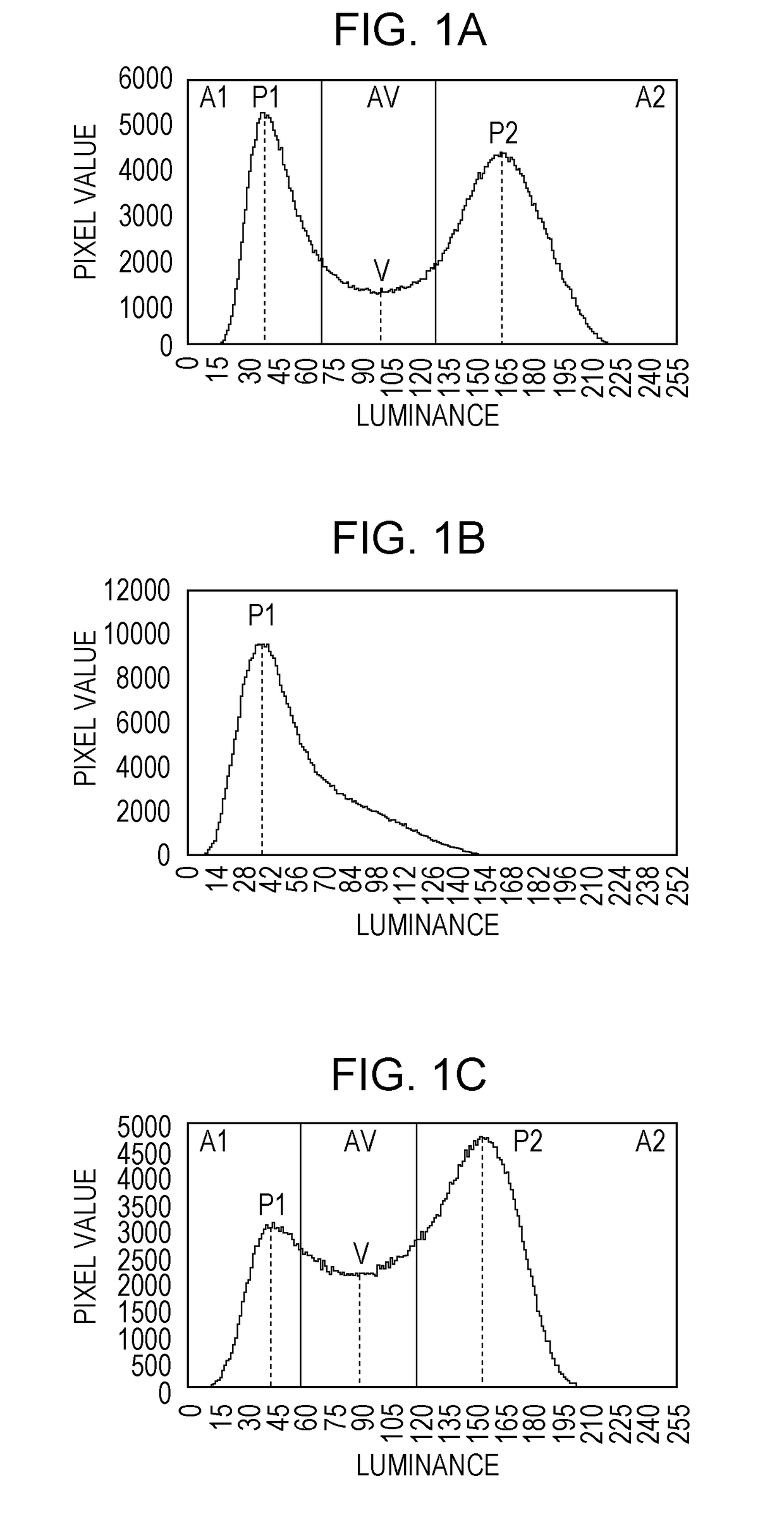
An image forming apparatus includes an image bearing member, a developing device, and an intermediate transfer member. The developing device includes a toner container containing a toner. The intermediate transfer member is charged to 3.0 nC/g or less in terms of absolute value at the surface thereof. The toner particles include a surface layer, and the brightness histogram of the toner particles has two local maximums P1 and P2 and a local minimum between P1 and P2. P2 is derived from the organosilicon polymer. P1 lies in a brightness range of 20 to 70, and P2 lies in a brightness range of 130 to 230. The number of pixels of P1 and the number of pixels of P2 are each 0.50% or more relative to the total number of pixels. The total numbers of pixels A1, AV, and A2 each in a specific brightness range satisfy specific relationships.

Description

BACKGROUND OF THE INVENTIONField of the Invention[0001]The present disclosure relates to an image forming apparatus using an electrophotographic system or an electrostatic recording system, such as a copy machine, a printer, or a facsimile machine, and to an image forming method using such a system.Description of the Related Art[0002]Further reduced power consumption and further improved image quality are desired for image forming apparatuses. To respond to this, various studies have been conducted for developing toners having high fixability and high transferability.[0003]For example, there has been devised a toner that is not likely to cause thin paper to stick to the heating member of the fuser while keeping good fixability at low temperature. Japanese Patent Laid-Open No. 2009-186640 discloses a toner including core particles coated with a resin shell layer in which a specific hole is formed for preventing sticking.[0004]However, the toner provided with only the shell layer have...

Claims


Application Information

Patent Timeline
Patent Type & Authority Applications(United States)
IPC IPC(8): G03G15/16
CPCG03G15/162G03G9/09328G03G9/09378G03G9/00
Inventor YAGI, YASUTAKAYOSHIDA, SARAMOCHIZUKI, SHINSUKETOMINAGA, TSUNEYOSHIKAMIKURA, KENTASHIMANO, TSUTOMU
Owner CANON KK
Why Eureka
Try Eureka