Solar cell and solar cell panel including the same

a solar cell and solar panel technology, applied in the field of can solve the problems of long-term reliability of solar cell panel, and achieve the effects of minimizing light loss, reducing energy consumption, and improving solar cell and solar cell panel output efficiency

Pending Publication Date: 2019-03-07
SHANGRAO JINKO SOLAR TECH DEV CO LTD
View PDF13 Cites 5 Cited by
  • Summary
  • Abstract
  • Description
  • Claims
  • Application Information

AI Technical Summary

Benefits of technology

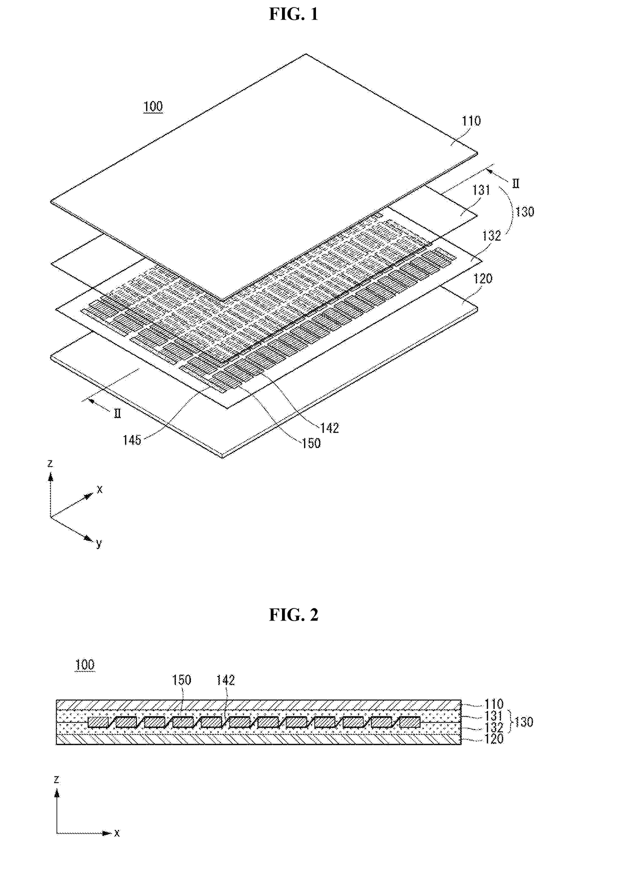
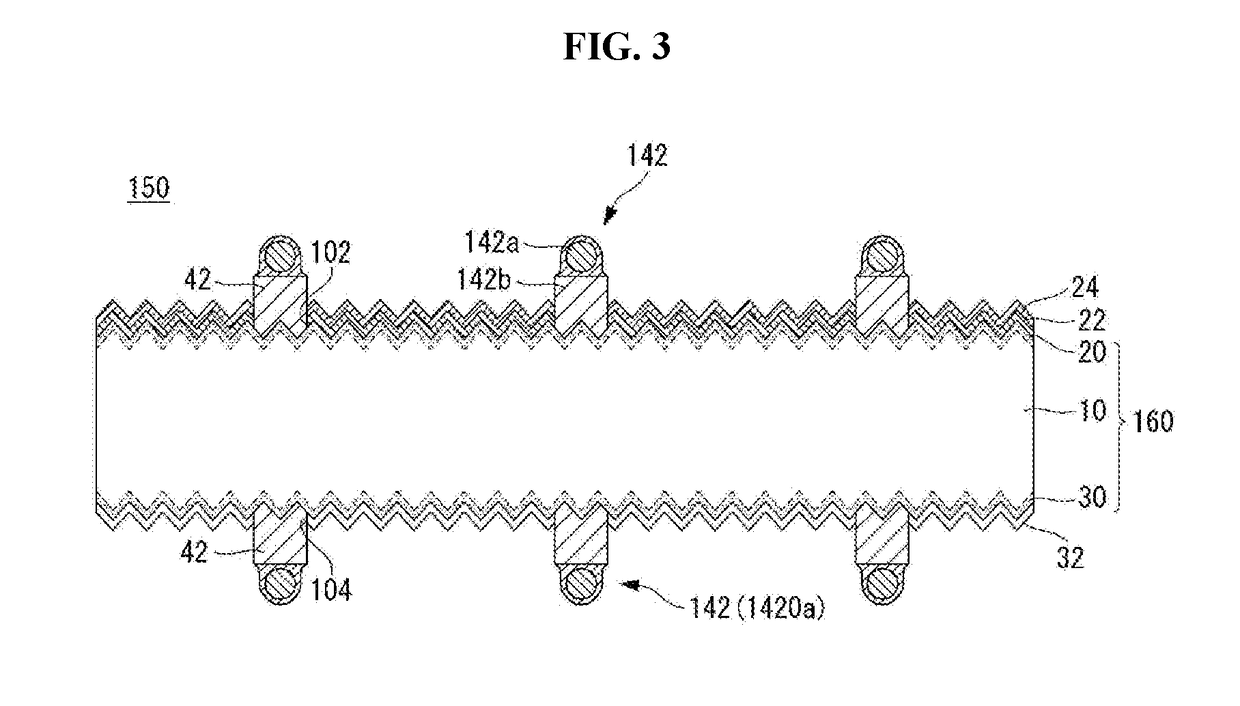
[0009]According to the embodiments, light loss can be minimized by using a bus bar having a small width and / or a lead having a wire shape, and a movement path of carriers can be reduced by increasing a number of bus bars and / or leads. Thus, efficiency of the solar cell and an output of the solar cell panel can be improved. Further, the light loss can be minimized due to diffused reflection or the like by using the lead having the wire shape, and the movement path of carriers can be reduced by reducing a pitch of the leads. Thus, the efficiency of the solar cell and the output of the solar cell panel can be improved.
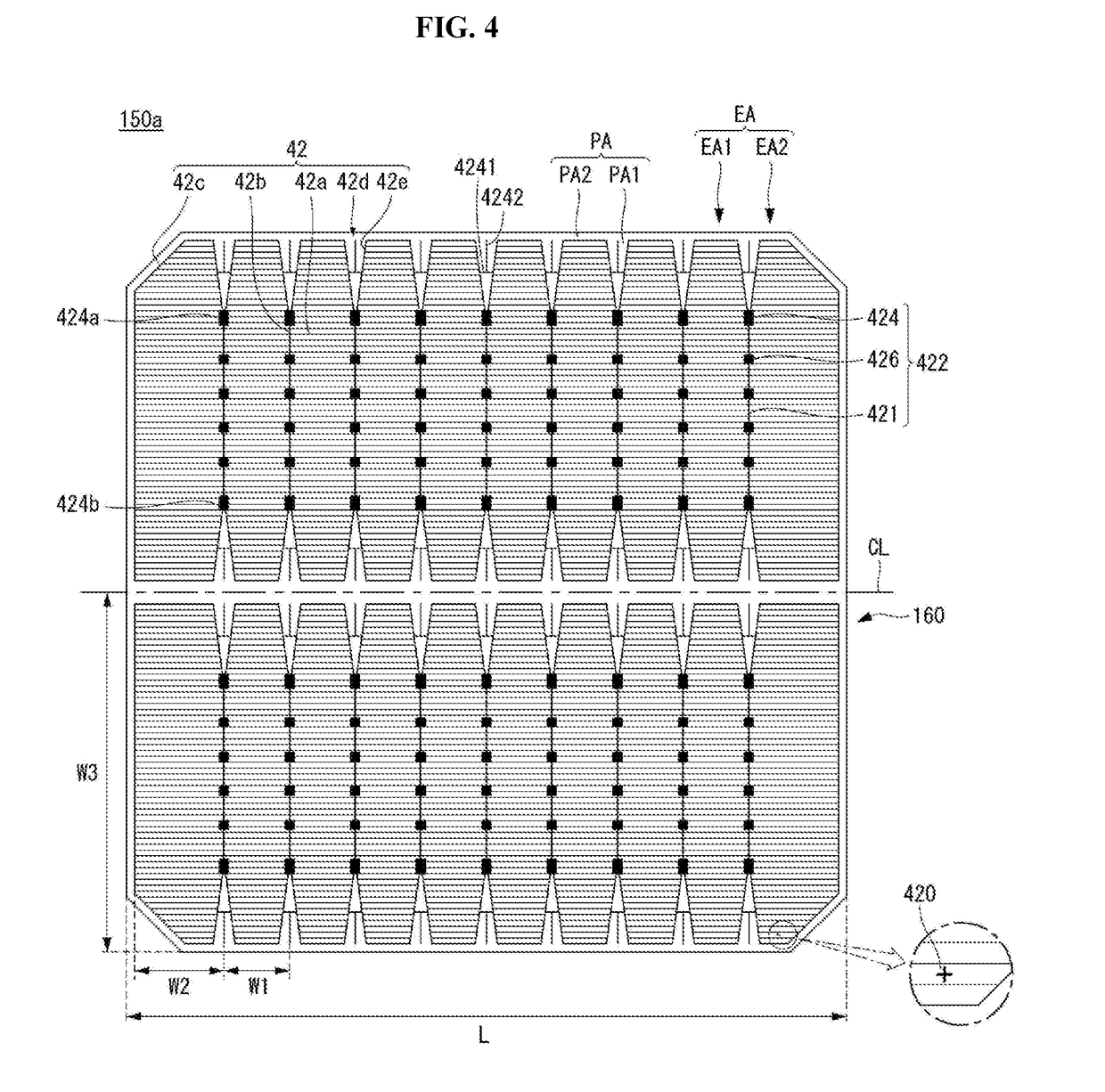
[0010]Particularly, the efficiency of the solar cell and the output of the solar cell panel can be maximized by applying the lead to the solar cell having a long axis and a short axis. In this instance, the lead may be arranged in a direction of the short axis and the outer pads may be positioned at both sides in the short axis direction. Then, the movement path through the lead can be minimized and the attachment property of the lead can be enhanced.

Problems solved by technology

Solar cell panels require long-term reliability because they must generate electricity for a longtime in various environments.

Method used


Image

  • Solar cell and solar cell panel including the same
  • Solar cell and solar cell panel including the same
  • Solar cell and solar cell panel including the same

Examples


Embodiment Construction

[0022]Reference will now be made in detail to various embodiments of the invention, examples of which are illustrated in accompanying drawings. The invention may, however, be embodied in many alternate forms and should not be construed as limited to the embodiments set forth herein.

[0023]In the drawings, illustration of parts unrelated to embodiments of the invention is omitted for clarity and simplicity of description. The same reference numerals designate the same or very similar elements throughout the specification. In the drawings, the thicknesses, widths or the like of elements are exaggerated or reduced for clarity of description, and should not be construed as limited to those illustrated in the drawings.

[0024]It will be understood that the terms “comprises” and / or “comprising,” or “includes” and / or “including” used in the specification specify the presence of stated elements, but do not preclude the presence or addition of one or more other elements. In addition, it will be...


PUM


Abstract

Disclosed is a solar cell panel including: a semiconductor substrate having a long axis and a short axis that intersect; a first conductivity type region formed on one surface of the semiconductor substrate; a second conductivity type region formed on the other surface of the semiconductor substrate; a first electrode electrically connected to the first conductivity type region; and a second electrode electrically connected to the second conductivity type region. The first electrode includes: a plurality of finger lines positioned in a first direction parallel to the long axis and being parallel to each other; and a plurality of bus bars including a plurality of pad portions positioned in a second direction parallel to the short axis. The plurality of pad portions include a first outer pad and a second outer pad located on opposite ends of the plurality of bus bars in the second direction, respectively.

Description

CROSS-REFERENCE TO RELATED APPLICATION[0001]This application is a continuation of U.S. application Ser. No. 15 / 633,107, filed on Jun. 26, 2017, which claims the priority benefit of Korean Patent Application No. 10-2016-0163559 filed on Dec. 2, 2016, the disclosures of which are incorporated herein by reference.BACKGROUND OF THE INVENTION1. Field of the Invention[0002]Embodiments of the invention relate to a solar cell and a solar cell panel including the same, and, more particularly, to a solar cell improved in structure and a solar cell panel including the same.2. Description of the Related Art[0003]Recently, as existing energy resources such as petroleum and coal are expected to be depleted, interest in alternative energy to replace them is increasing. Among them, solar cells are attracting attention as a next-generation battery that converts solar energy into electric energy.[0004]A plurality of solar cells are connected in series or in parallel by a ribbon, and are then packaged...

Claims


Application Information

Patent Timeline
Patent Type & Authority Applications(United States)
IPC IPC(8): H01L31/0224H01L31/05H01L51/44H01L31/02H01L31/06H01L31/048H01L31/0352
CPCH01L31/0508H01L51/447H01L31/022433H01L31/0504H01L31/022441H01L31/022425H01L31/0201H01L31/06H01L31/048H01L31/0352Y02E10/549Y02P70/50H01L31/02002H01L31/042H01L31/05Y02E10/50H10K30/87
Inventor YOON, PHILWONCHANG, JAEWONKIM, JINSUNG
Owner SHANGRAO JINKO SOLAR TECH DEV CO LTD
Why Eureka
Try Eureka