Liquid ejecting head, liquid ejecting apparatus, and piezoelectric device

Active Publication Date: 2019-03-14
SEIKO EPSON CORP
View PDF3 Cites 1 Cited by
  • Summary
  • Abstract
  • Description
  • Claims
  • Application Information

AI Technical Summary

Benefits of technology

[0008]An advantage of some aspects of the invention is to provide a liquid ejecting head, a liquid ejecting apparatus, and a piezoelectric device capable of in

Problems solved by technology

However, if a filler such as an underfill agent provided between a drive circuit and a flow path forming substrate is covered with a protective film for protecting the flow path forming substrate from ink, the gas emitted from the filler is not discharged to the outside, so that contamination occurs on a surface of a wiring connected to a terminal and a terminal of the drive circuit, so that there is a problem that short-circuiting or dielectric breakdown of the wiring is likely to occur.
In addition, there is a problem that adhesion of the bonding surface between the drive circuit and the flow path forming substrate deteriorates due to the gas emitted from the filler and migration is likely to occur.
Such a problem is not limited to

Method used


Image

  • Liquid ejecting head, liquid ejecting apparatus, and piezoelectric device
  • Liquid ejecting head, liquid ejecting apparatus, and piezoelectric device
  • Liquid ejecting head, liquid ejecting apparatus, and piezoelectric device

Examples


Example

Embodiment 1

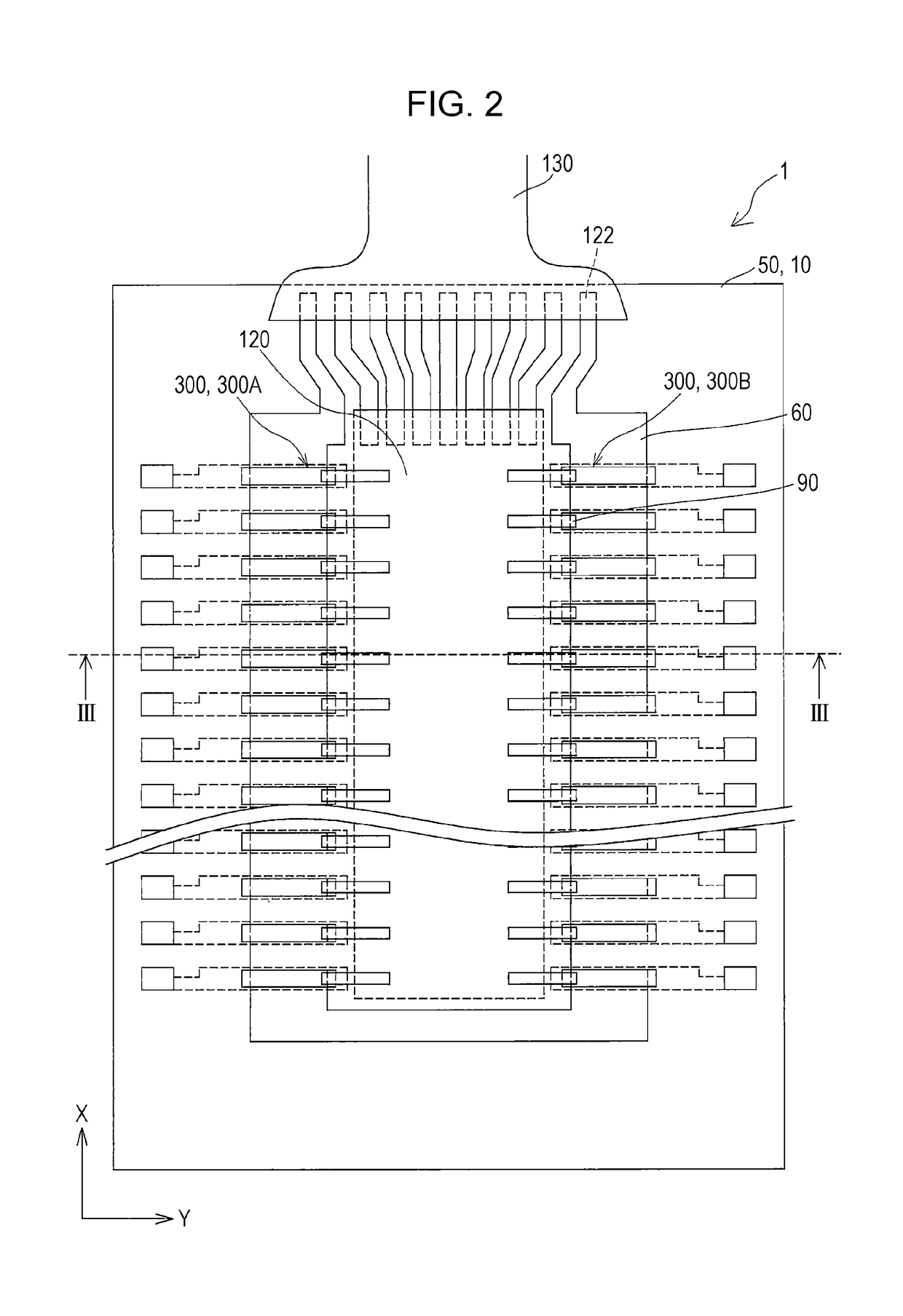
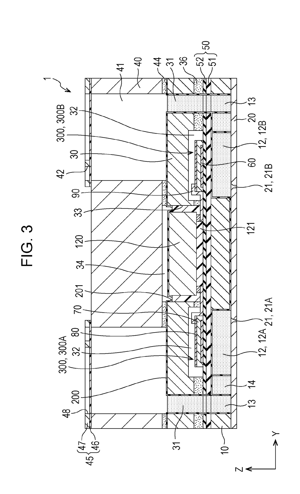
[0033]FIG. 1 is an exploded perspective view of an ink jet type recording head which is an example of a liquid ejecting head according to Embodiment 1 of the invention, FIG. 2 is a plan view of a flow path forming substrate of the ink jet type recording head, FIG. 3 is a cross-sectional view of the ink jet type recording head conforming to a line III-III of FIG. 2, and FIG. 4 is an enlarged view of a main part of FIG. 3.

[0034]As shown in the drawing, as a flow path forming substrate 10 constituting an ink jet type recording head 1 (hereinafter, simply referred to as recording head 1), a metal such as stainless steel, nickel (Ni), ceramic materials represented by zirconium oxide (ZrOX) or aluminum oxide (AlXOY), glass ceramic materials, oxide such as silicon oxide (SiOX), magnesium oxide (MgO), lanthanum aluminate (LaAlO3), or the like can be used. In the embodiment, the flow path forming substrate 10 is made of a silicon single crystal substrate.

[0035]The flow path formi...

Example

Embodiment 2

[0087]FIG. 8 is a cross-sectional view of an ink jet type recording head which is an example of a liquid ejecting head according to Embodiment 2 of the invention. The same reference numerals are given to members similar to those in the above-described embodiment, and redundant explanations are omitted.

[0088]As shown in FIG. 8, in the recording head 1 of the embodiment, the recessed portion 202 is formed in the protective film 200 provided on the bonding surface of the protective substrate 30 with the case member 40.

[0089]The recessed portion 202 is not formed in the boundary portion between the bonding surfaces of the third liquid supply chamber 41 and the case member 40 but is formed in a portion other than the boundary. In the embodiment, a plurality of recessed portions 202 are disposed in parallel in the first direction X on the bonding surface of the protective substrate 30 with the case member 40.

[0090]Such a recessed portion 202 may be formed by completely removin...

Example

Embodiment 3

[0093]FIG. 9 is a cross-sectional view of an ink jet type recording head which is an example of a liquid ejecting head according to Embodiment 3 of the invention. The same reference numerals are given to members similar to those in the above-described embodiment, and redundant explanations are omitted.

[0094]As shown in FIG. 9, an atmosphere release path 43 that communicates the space 34 holding the drive circuit 120 with the outside is formed in the case member 40, which is the flow path member of the embodiment. In the embodiment, the atmosphere release path 43 is provided penetrating the case member 40 in the third direction Z. That is, one end of the atmosphere release path 43 is provided so as to the space 34, and the other end thereof is provided so as to open on the side opposite to the protective substrate 30 of the case member 40.

[0095]In addition, in the protective film 200, similarly to Embodiment 1, the exposure hole 201 exposing at least a portion of the surf...


PUM


Abstract

A liquid ejecting head includes a flow path forming substrate, a vibration plate that is formed on one surface side of the flow path forming substrate, a plurality of piezoelectric elements that are provided on the vibration plate, a protective substrate that is bonded to the one surface side of the flow path forming substrate and has a flow path, a flow path member that is bonded to a side of the protective substrate opposite to the flow path forming substrate, a drive circuit that is mounted in a space formed so as to be surrounded by the flow path forming substrate, the protective substrate, and the flow path member, a filler that is filled between the drive circuit and the protective substrate, and a protective film that is formed on an inner wall, in which the protective film has an exposure hole exposing a surface of the filler.

Description

[0001]The entire disclosure of Japanese Patent Application No. 2017-175476, filed Sep. 13, 2017 is expressly incorporated by reference herein.BACKGROUND1. Technical Field[0002]The present invention relates to a liquid ejecting head that ejects a liquid, a liquid ejecting apparatus including the liquid ejecting head, and a piezoelectric device including a piezoelectric element.2. Related Art[0003]As a piezoelectric device used in an ink jet type recording head which is a typical example of a liquid ejecting head, there is a device including an individual flow path communicating with a nozzle, a flow path forming substrate provided with a liquid supply chamber communicating with the individual flow path, and a piezoelectric element provided on one surface side of the flow path forming substrate via a vibration plate.[0004]An ink jet type recording head having such a piezoelectric device has been proposed in which a drive circuit for driving a piezoelectric element is directly mounted ...

Claims


Application Information

Patent Timeline
IPC IPC(8): B41J2/14
CPCB41J2/14233B41J2002/14306B41J2/01B41J2/14201H10N30/20B41J2/1606B41J2/161B41J2/1623B41J2/1628B41J2/1642B41J2/1646B41J2002/14419B41J2002/14491
Inventor NAKAYAMA, MASAOFUKUDA, SHUNYAHIRAI, EIJUYAZAKI, SHIRONAKAO, HAJIME
Owner SEIKO EPSON CORP
Why Eureka
Try Eureka