Voltage regulator circuit and method therefor

a voltage regulator and circuit technology, applied in the direction of electric variable regulation, process and machine control, instruments, etc., can solve the problems of supply voltage, limited life time, and longer device li

Active Publication Date: 2019-03-14
NXP BV
View PDF1 Cites 12 Cited by
  • Summary
  • Abstract
  • Description
  • Claims
  • Application Information

AI Technical Summary

Problems solved by technology

A connected device is generally powered by a battery, which has a limited life time, depending on the current consumption of the said connected device.
As a result, the lower the current consumption, the longer the device life time, and this has led to use of LDO supply voltages.
Dependent upon the process node, it is not always possible to benefit from very low leakage digital libraries (generally using GO2 devices), and as a result GO1-based digital cells have to be used.
When supplied with their nominal voltage (e.g. 1.1V in a 40 nm process), they are known to ‘leak’ current much more than the IoT standard allows.
This is especially the case when the digital design represents a relatively large number of cells, e.g. large enough to impact the total current consumption due to the cells' leakage.
Thus, any sudden Iload increase turns into an uncompensated drop at the LDO output, at least temporarily.
It can easily be figured out by a person skilled in the art that the output of a conventional weakly biased LDO will not be regulated well with this type of varying load current.
Notably, it is unsuitable for an ultra-low power design, as a lot of current hungry circuitry is needed, and, not least that the design requires ˜3 μA @ zero load current.

Method used


Image

  • Voltage regulator circuit and method therefor
  • Voltage regulator circuit and method therefor
  • Voltage regulator circuit and method therefor

Examples


Embodiment Construction

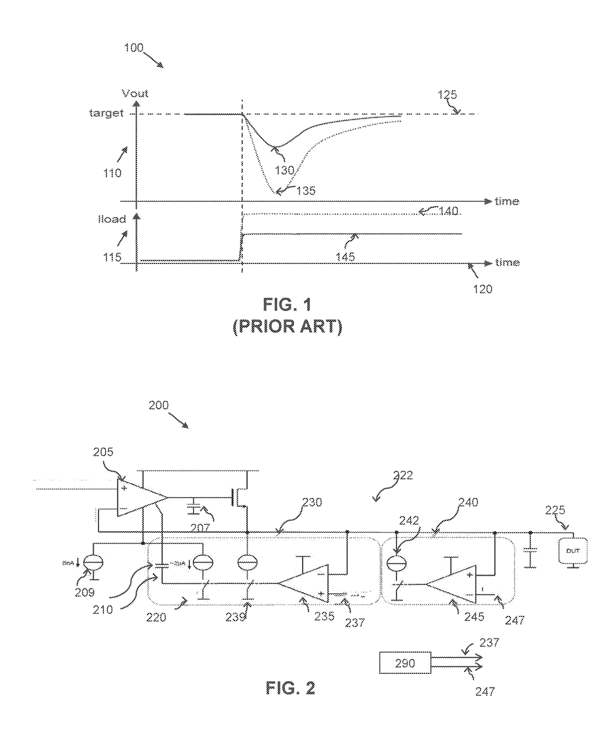
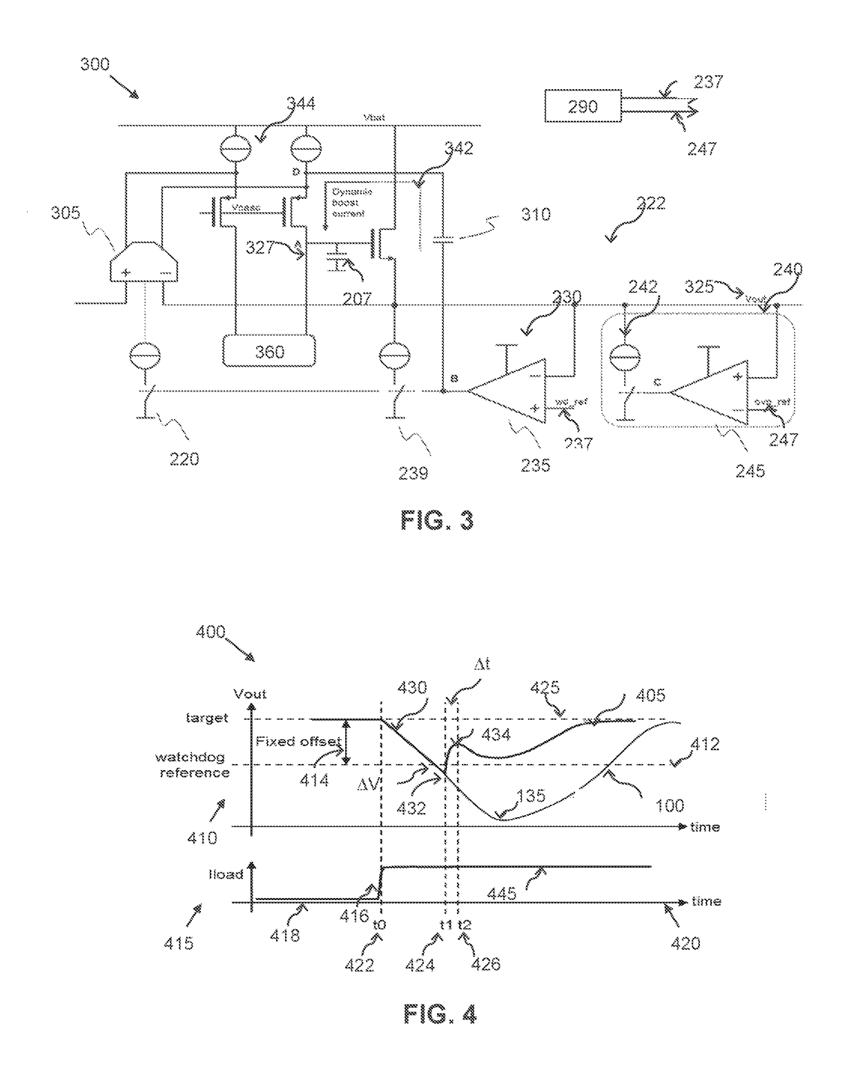
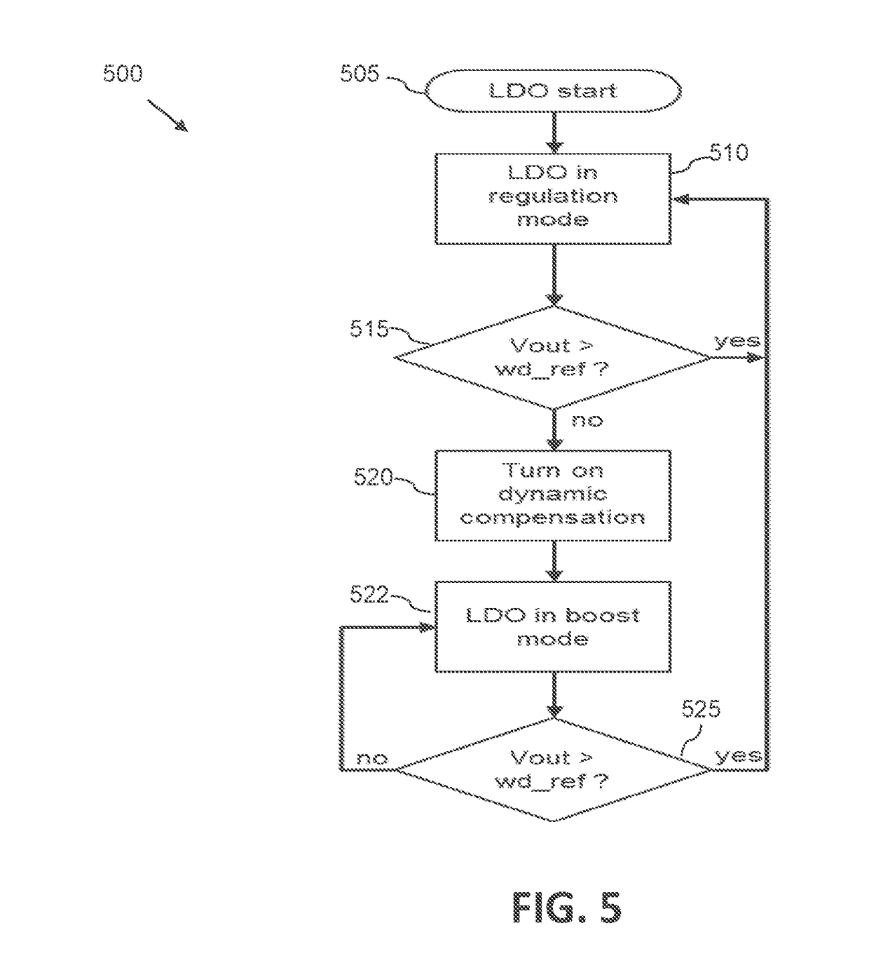
[0027]The present invention will now be described with reference to an LDO topology suitable for use in an ultra-low power CMOS LDO with fast transient response, for example for use with IoT circuits. Examples of the invention propose a use of a regulation adjustment circuit operably coupled to an output of the high gain amplifier of the LDO and configured to dynamically react to any transition of the regulated output outside of a desired regulated voltage range. The regulation adjustment circuit functions as one or more additional feedback loops that reside outside of the main feedback loop of the LDO. Some examples of the invention propose a watchdog loop as the regulation adjustment circuit, configured to detect when the output voltage goes too low, and in response thereto boosts the LDO biasing until the voltage has gone sufficiently high. Advantageously, a watchdog loop that is located outside of the main feedback loop is able to compensate for a very slow response of an LDO du...


PUM


Abstract

A low drop out, LDO, voltage regulator circuit is that includes a high gain amplifier configured to receive a current biasing signal and arranged to regulate the voltage supply signal and output a regulated voltage supply signal. A regulation adjustment circuit is operably coupled to an output of the high gain amplifier and includes a comparator configured to compare the output regulated voltage supply signal with a threshold, wherein an output of the comparator is configured to perform one of: (i) supply a dynamic current boost to the LDO current biasing signal, in response to the regulated voltage supply signal voltage dropping below the threshold; (ii) activate a dynamic current pull down circuit to reduce an over voltage output of the LDO voltage regulator circuit in response to the regulated voltage supply signal voltage exceeding the threshold.

Description

FIELD OF THE INVENTION[0001]The field of this invention relates to a voltage regulator circuit and method therefor. In particular, in some examples, the field of this invention relates to an ultra-low power complementary metal oxide semiconductor (CMOS) low drop-out (LDO) voltage regulator circuit with a fast transient response.BACKGROUND OF THE INVENTION[0002]Power supply circuits within modern integrated circuit (IC) devices are often required to generate a constant, stable output voltage, typically from a varying input voltage. For example, in automotive applications a power supply circuit may be required to generate a regulated 7V output voltage from an input voltage from a battery comprising a voltage level ranging from, say, a nominal battery voltage of 14V down to 2.5V. Thus, low drop out voltage regulator circuits that provide a regulated supply voltage to circuits and functions have become popular.[0003]With respect to LDO voltage regulator circuits, GO2 is an NMOS or PMOS ...

Claims


Application Information

Patent Timeline
Patent Type & Authority Applications(United States)
IPC IPC(8): G05F1/575G05F1/571
CPCG05F1/575G05F1/571G05F1/56
Inventor TOURRET, JEAN-ROBERT
Owner NXP BV
Why Eureka
Try Eureka