System and method of continuous health monitoring

Inactive Publication Date: 2019-03-21
KARNIK PRASAD +1
View PDF0 Cites 16 Cited by
  • Summary
  • Abstract
  • Description
  • Claims
  • Application Information

AI Technical Summary

Benefits of technology

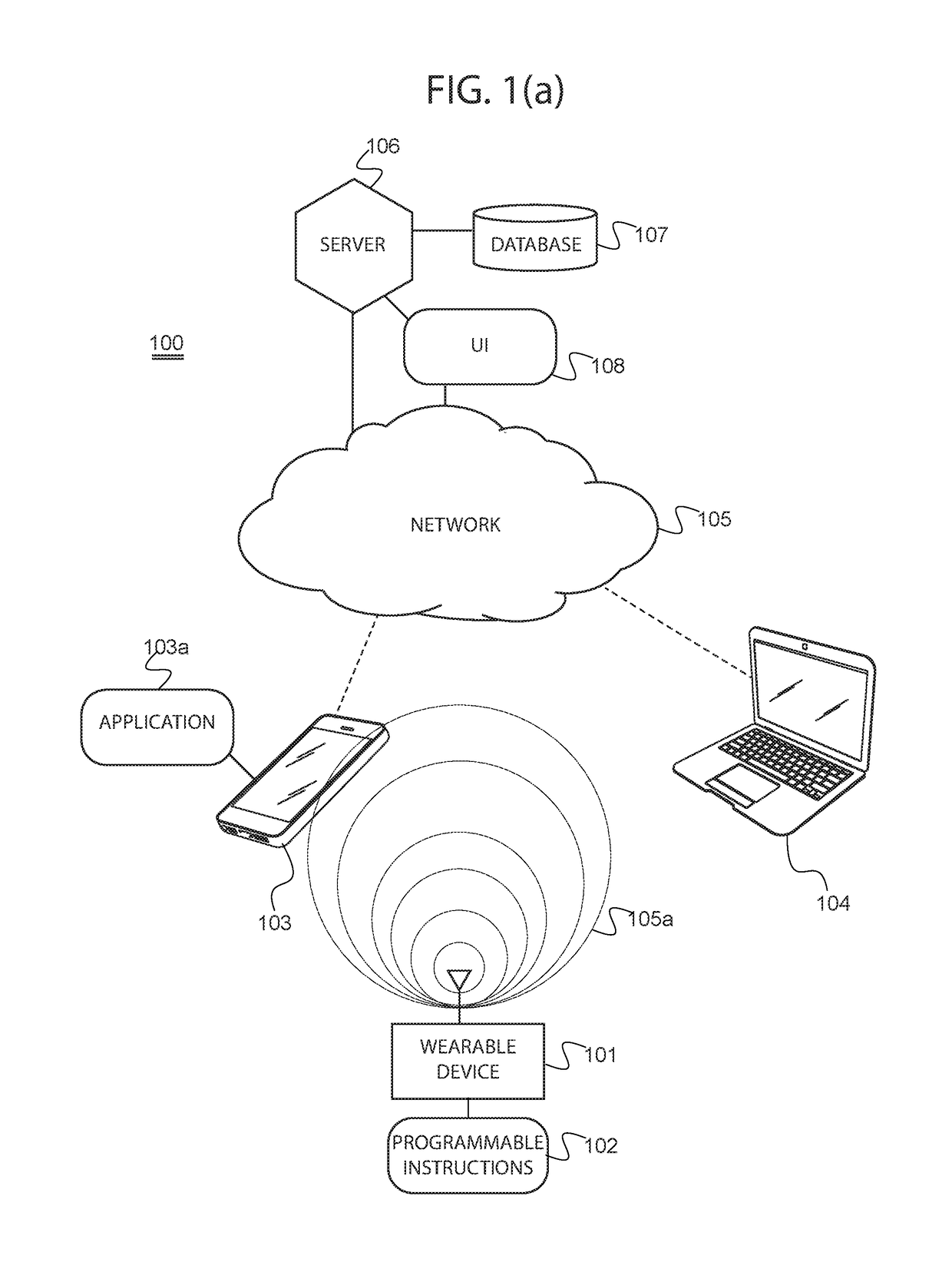
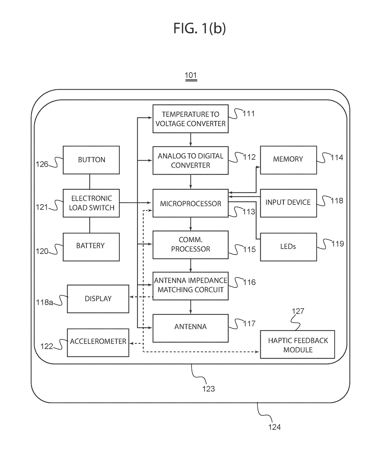
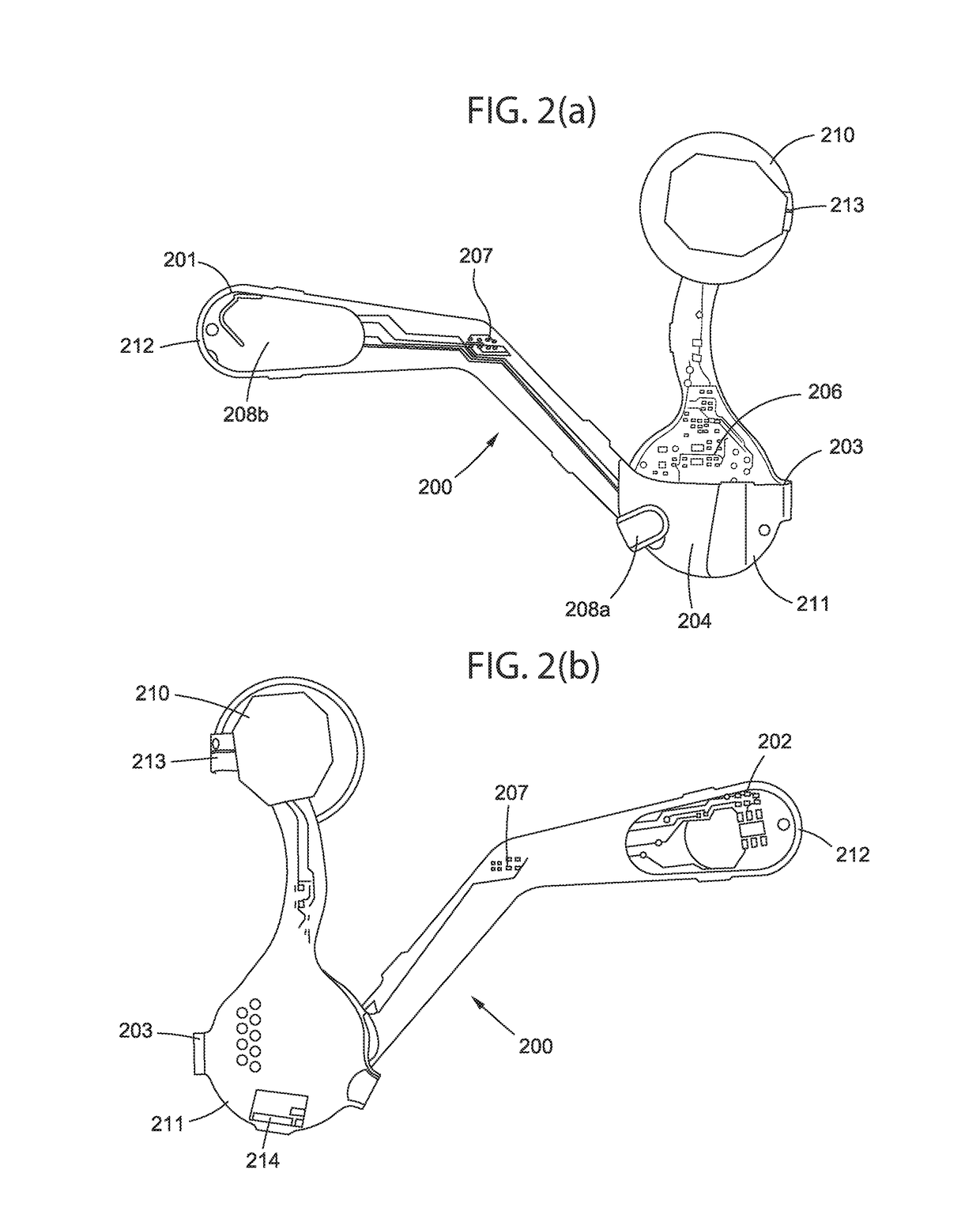
[0018]Generally, the invention involves a system comprising at least one wearable device that employs a flexible printed circuit board (PCB), which includes a temperature sensor. The flexible PCB may be printed on a flexible substrate that may be folded to form multiple layers configured to house the sensor and an antenna. The sensor may be housed within said layers and situated at a terminal end of a pathway that may be printed on the PCB, which conducts heat from the body of the user to the sensor. The antenna may be housed within the layers of the flexible PCB in a manner such that proper signal transmission is preserved, and latency is minimized. A part of the flexible PCB may be folded around a battery to connect to the terminals of the battery. Temperature readings may be wirelessly communicated to one or more client devices, which implement one or more algorithms suitable for generating insights regarding one or more health aspects of the user. The system may also further comprise another wearable device suitable for reading multiple voltage differentials throughout the human body of a user. In exemplary embodiments, such wearable device may comprise a plurality of contacts, some of which may be applied directly to the body and some of which may be disposed on a surface of the device for a user to interact with. A multiplexer in communication with a microprocessor housed within the wearable device may be used to receive and process the voltage differences; a communications module may transmit the voltage differentials to one or more client devices. As may be appreciated, these signals pertaining to voltage differentials throughout the body may be utilized to detect abnormalities indicative of a health condition, and or used for monitoring the health of the user. In certain embodiments, the voltage differe

Problems solved by technology

Other metrics are more difficult to read with popular devices such as the smart watches and fitness bands of today.
For example, many smart watches and fitness bands fail to include hardware that reads certain critical vital signs—like body temperature.
Reading the body's core temperature accurately is not easily achieved by placing a sensor in just any area of the human body; for example, a smart watch equipped with a temperature sensor for example is unlikely to properly read a user's body core temperature because the wrist is not a medically recognized region for accurately taking temperature measurements—accordingly, any reading of temperature may simply be undependable with common wearables.
Yet, these devices are riddled with shortcomings.
One persistent problem in body-worn wearable devices is the design and placement of antennas.
For example, some devices, designed to be placed at the axillary region, fail in function because the axillary region is an enclosed cavity surrounded by body tissue that severely attenuates radio frequency signal, thereby rendering the device unable to properly transmit the temperature measured to a listening device.
Another problem is the delay in getting an accurate measurement of body temperature after applying the device on the body.
Any measurement means that uses a temperature sensor suffers latency that comes from having to get the temperature sensor in thermal equilibrium with the body—usually causing a delay in the order of minutes.
This delay is not acceptable to users who are looking for an accurate reading in seconds.
Part of the problem resides in the material and means used for conducting heat.
Yet another problem is providing proper battery life suitable for effective continuous health care monitoring; battery life is a challenge for wearable devices and has not been adequately addressed.
The power consumed by these devices is still too high to allow wearable devices to last for many months without recharging or without using a large and intrusive primary battery.
For a wearable device

Method used


Image

  • System and method of continuous health monitoring
  • System and method of continuous health monitoring
  • System and method of continuous health monitoring

Examples


Example

[0059]In the following discussion that addresses a number of embodiments and applications of the present invention, reference is made to the accompanying drawings that form a part thereof, where depictions are made, by way of illustration, of specific embodiments in which the invention may be practiced. It is to be understood that other embodiments may be utilized and changes may be made without departing from the scope of the invention. Wherever possible, the same reference numbers are used in the drawings and the following description to refer to the same or similar elements.

[0060]Conditional language used herein, such as, among others, “can,”“could,”“might,”“may,”“e.g.,” and the like, unless specifically stated otherwise, or otherwise understood within the context as used, is generally intended to convey that certain embodiments include, while other embodiments do not include, certain features, elements and / or steps. Thus, such conditional language is not generally intended to im...


PUM


Abstract

The invention involves a system and method implementing a wearable device that employs a flexible printed circuit board (PCB), which includes a temperature sensor. The PCB may be printed on a flexible substrate that may be folded to form multiple layers configured to house the sensor and an antenna. The sensor may be housed within said layers and situated at a terminal end of a pathway that may be printed on the PCB, wherein the pathway acts as a contact as well as a conduit of heat from the body of the user to the sensor. The antenna may be housed within the layers of the flexible PCB in a manner such that proper signal transmission is preserved and latency is minimized. Temperature readings may be wirelessly communicated to one or more client devices, which implement one or more algorithms suitable for generating insights regarding health aspects of the user.

Description

PRIORITY NOTICE[0001]The present application claims priority under 35 U.S.C. § 119 to U.S. Provisional Application 62 / 558,995, filed Sep. 15, 2017, the disclosure of which is incorporated herein by reference in its entirety.TECHNICAL FIELD OF THE INVENTION[0002]The present invention relates in general to a system and method of continuous health monitoring, and more specifically, to continuous health monitoring using a wearable device that wirelessly communicates electrical activity, which may be in conjunction with improved temperature readings, to one or more client devices.COPYRIGHT AND TRADEMARK NOTICE[0003]A portion of the disclosure of this patent application may contain material that is subject to copyright protection. The owner has no objection to the facsimile reproduction by anyone of the patent document or the patent disclosure, as it appears in the Patent and Trademark Office patent file or records, but otherwise reserves all copyrights whatsoever.[0004]Certain marks refe...

Claims


Application Information

Patent Timeline
IPC IPC(8): A61B5/01A61B5/00G16H80/00G06F3/0482
CPCA61B5/01A61B5/0008G16H80/00G06F3/0482A61B5/4306A61B5/6831A61B5/6833A61B5/6804A61B2562/0271A61B2562/166G16H40/63G16H40/67A61B5/6832A61B5/742A61B5/002A61B2562/164G16H50/30G16H20/30G06F1/163G06F1/1698G06F1/1684G06F3/002G06F3/011G06F3/016H05K1/189G06F1/188G06F1/183H05K2201/10151G01K13/20H05K2201/10098H05K1/165H05K1/028H05K1/181A61B5/6801H05K1/0206
Inventor KARNIK, PRASADPATHARE, SUMUKH
Owner KARNIK PRASAD
Why Eureka
Try Eureka