Cell culture device and cell culture method

a cell culture and cell technology, applied in the field of culturing cells, can solve the problems of increasing the cost of developing chemical products such as cosmetics, and increasing the success rate of clinical trials. , to achieve the effect of simplifying the structure of the device, simplifying the flow path, and miniaturizing the devi

Active Publication Date: 2019-03-28
NAT INST OF ADVANCED IND SCI & TECH
View PDF1 Cites 7 Cited by
  • Summary
  • Abstract
  • Description
  • Claims
  • Application Information

AI Technical Summary

Benefits of technology

[0043]According to an aspect of the present invention, it is possible to introduce the culture liquid from the first culture liquid storage chamber into the culture liquid main chamber through the culture liquid introduction flow path by pressurizing the first culture liquid storage chamber and culture cells on the membrane in the culture liquid main chamber while exposing the cells to fluid shear stress, and it is possible to introduce the culture liquid in the culture liquid main chamber into the second culture liquid storage chamber through the culture liquid lead-out flow path. For this reason, it is possible to simplify the structure of the flow path of liquid transfer. Accordingly, it is possible to miniaturize the device by simplifying the structure of the device and to facilitate the operation.
[0044]According to the cell culture device having a plurality of cell culture units, it is possible to perform a plurality of tests in parallel through a simple operation. For this reason, it is possible to efficiently evaluate a large number of specimens (drugs and the like).

Problems solved by technology

As described in Non-Patent Documents 1 and 2, development cost for pharmaceutical products in recent years has increased exponentially, and the success rate of clinical trials has decreased year by year.
In addition, the cost for developing chemical products such as cosmetics has similarly increased.
As the reason for this, for example, due to the species difference between animals and humans, results of animal experiments cannot be directly extrapolated to clinical trials.
In addition, in the development of chemical products such as cosmetics, in some cases, it is difficult to use experimental animals, especially in Europe.
On the other hand, monolayer culture used in cell assays in the conventional art is often problematic in that the environment surrounding cells is greatly different from the in vivo environment, and therefore, many functions expressed in a body are lost in cultured cells.
However, in these culture containers, a liquid cannot flow on one surface side and the other surface side of the membrane.
Therefore, there are problems in that a physiological function is not exhibited, the conditions of cells in the lower portion of the membrane are deteriorated, and the culture containers cannot be applied to body-on-a-chip in which a plurality of organs are linked to each other.
On the other hand, a syringe pump or a peristaltic pump is used for liquid transfer in the above-described prior research, and therefore, it is difficult to parallelize the culture system.

Method used


Image

  • Cell culture device and cell culture method
  • Cell culture device and cell culture method
  • Cell culture device and cell culture method

Examples


first embodiment

[0059][Cell Culture Device] A cell culture device 10 of a first embodiment will be described with reference to the drawings.

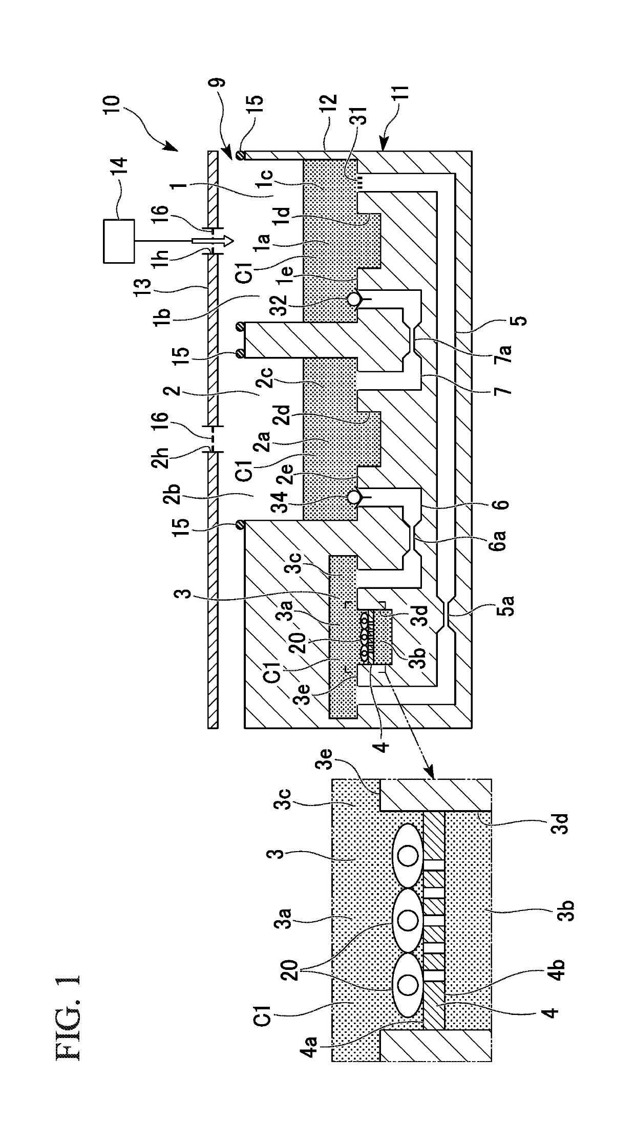
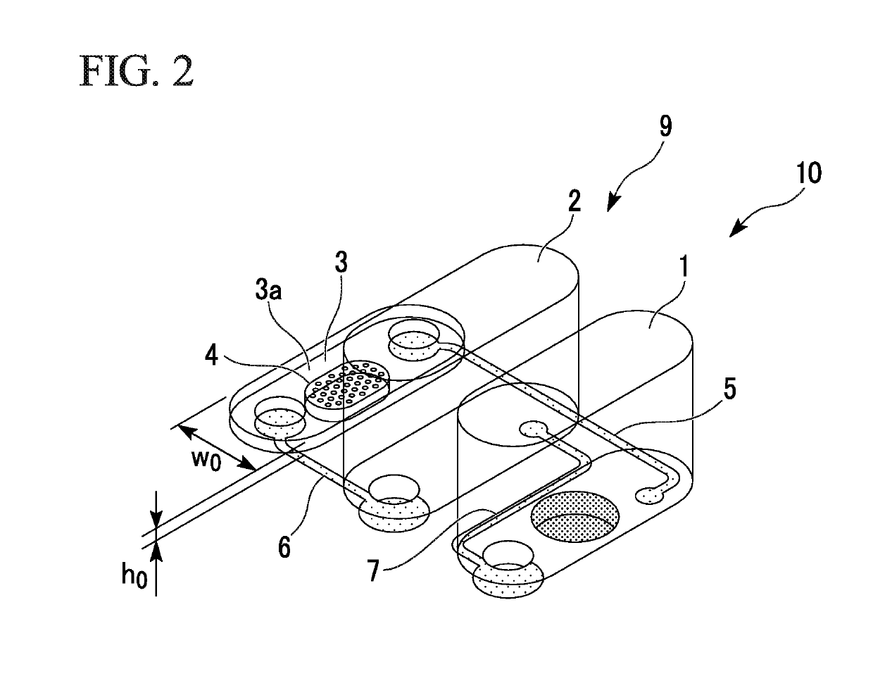
[0060]FIG. 1 is a cross-sectional view schematically showing the cell culture device 10. FIG. 2 is a perspective view schematically showing the cell culture device 10.

[0061]As shown in FIGS. 1 and 2, the cell culture device 10 includes a storage tank 11 and a pressurizing pump 14. The storage tank 11 includes one cell culture unit 9. The storage tank 11 includes a container-shaped tank main body 12 and a lid portion 13.

[0062]The cell culture unit 9 has a culture liquid main chamber 3, a first culture liquid storage chamber 1, a second culture liquid storage chamber 2, a membrane 4, a culture liquid introduction flow path 5, a culture liquid lead-out flow path 6, and a communication flow path 7.

[0063]The culture liquid main chamber 3 has a main chamber 3c and a recess portion 3d formed in a bottom surface 3e of the main chamber 3c.

[0064]The internal space of th...

second embodiment

[Cell Culture Device]

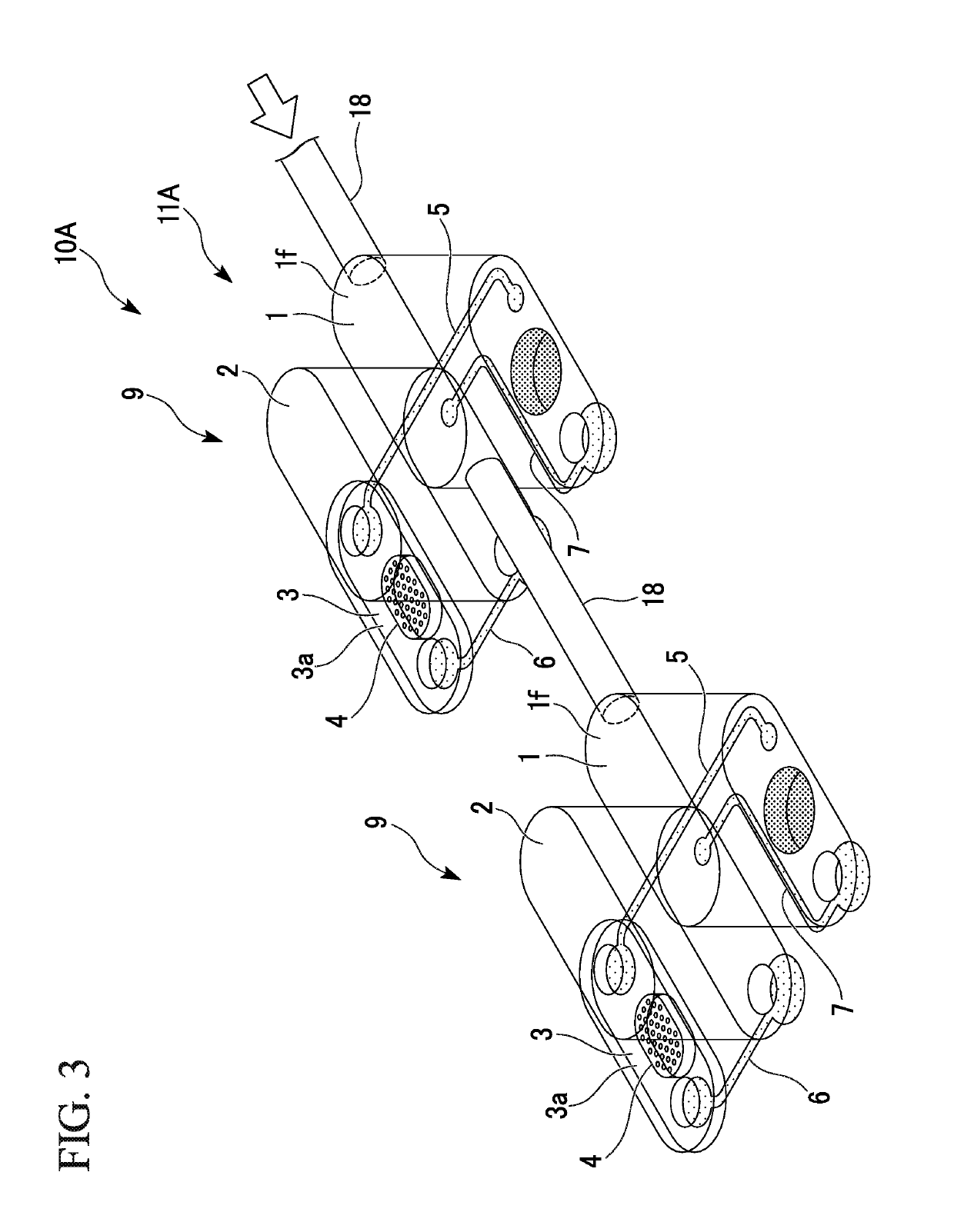
[0115]A cell culture device 10A according to a second embodiment will be described with reference to the drawings. Hereinafter, the same configurations as those described above are given the same reference numerals, and the description thereof will not be repeated.

[0116]As shown in FIG. 3, a storage tank 11A in the cell culture device 10A has a plurality of cell culture units 9. The number of cell culture units 9 may be any number of two or more.

[0117]Among the plurality of cell culture units 9, first culture liquid storage chambers 1 and 1 of two adjacent cell culture units 9 and 9 are connected with each other through a gas flow path 18 (connection flow path).

[0118]One end and the other end of the gas flow path 18 are connected to upper gas phase spaces if and if in the first culture liquid storage chambers 1 and 1, and therefore, the gas flow path 18 is connected to the first culture liquid storage chambers 1 and 1 so that gas is able to flow therethrough.

[01...

third embodiment

[Cell Culture Device]

[0125]A cell culture device 10B of a third embodiment will be described with reference to the drawings.

[0126]FIG. 4 is a cross-sectional view schematically showing the cell culture device 10B.

[0127]As shown in FIG. 4, the cell culture device 10B includes a storage tank 11B and a pressurizing pump (not shown in the drawings). The storage tank 11B includes one cell culture unit 9B. The storage tank 11B includes a tank main body 12B and a lid portion 13B.

[0128]The cell culture unit 9B has a culture liquid main chamber 3, a first culture liquid storage chamber 1, a second culture liquid storage chamber 2, a membrane 4, a culture liquid introduction flow path 5, a culture liquid lead-out flow path 6, a communication flow path 7, a first liquid storage chamber 21, a second liquid storage chamber 22, a liquid introduction flow path 25, a liquid lead-out flow path 26, and a communication flow path 27.

[0129]The first liquid storage chamber 21 and the second liquid storag...


PUM

PropertyMeasurementUnit
thicknessaaaaaaaaaa
shear stressaaaaaaaaaa

Abstract

A cell culture device includes a storage tank having one or a plurality of cell culture units. The cell culture units includes a culture liquid main chamber having a circulation space through which a culture liquid of cells circulates, a permeable membrane having one surface to which the cells are able to adhere, said one face facing the circulation space, a first culture liquid storage chamber having an airtight structure in which the culture liquid is to be stored, a second culture liquid storage chamber in which the culture liquid is to be stored, a culture liquid introduction flow path that introduces the culture liquid from the first culture liquid storage chamber into the circulation space of the culture liquid main chamber, and a culture liquid lead-out flow path that introduces the culture liquid from the circulation space into the second culture liquid storage chamber.

Description

TECHNICAL FIELD[0001]The present invention relates to a device of culturing cells and a method of culturing cells using the device.[0002]Priority is claimed on Japanese Patent Application No. 2016-45024, filed on Mar. 8, 2016, the content of which is incorporated herein by reference.BACKGROUND ART[0003]As described in Non-Patent Documents 1 and 2, development cost for pharmaceutical products in recent years has increased exponentially, and the success rate of clinical trials has decreased year by year. In addition, the cost for developing chemical products such as cosmetics has similarly increased. As the reason for this, for example, due to the species difference between animals and humans, results of animal experiments cannot be directly extrapolated to clinical trials. In addition, in the development of chemical products such as cosmetics, in some cases, it is difficult to use experimental animals, especially in Europe. Under such circumstances, there are increasing expectations ...

Claims


Application Information

Patent Timeline
Patent Type & Authority Applications(United States)
IPC IPC(8): C12M1/00C12M1/02C12M1/12
CPCC12M23/34C12M27/00C12M25/02C12M29/20
Inventor SUGIURA, SHINJISATOH, TAKUKANAMORI, TOSHIYUKISHIN, KAZUMI
Owner NAT INST OF ADVANCED IND SCI & TECH
Why Eureka
Try Eureka