
Incinerating system

a technology of incinerator and flare, which is applied in the direction of combustion type, combustion of lump and pulverulent fuel, lighting and heating apparatus, etc., can solve the problems of inability to store for a later use, situations that may require their destruction, etc., and achieve the effect of enhancing the incineration of fuel

Active Publication Date: 2019-04-04
ATLANTIS RES LABS INC
View PDF0 Cites 1 Cited by
  • Summary
  • Abstract
  • Description
  • Claims
  • Application Information

AI Technical Summary

Benefits of technology

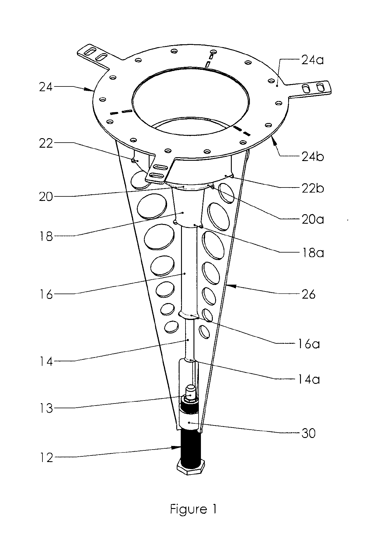
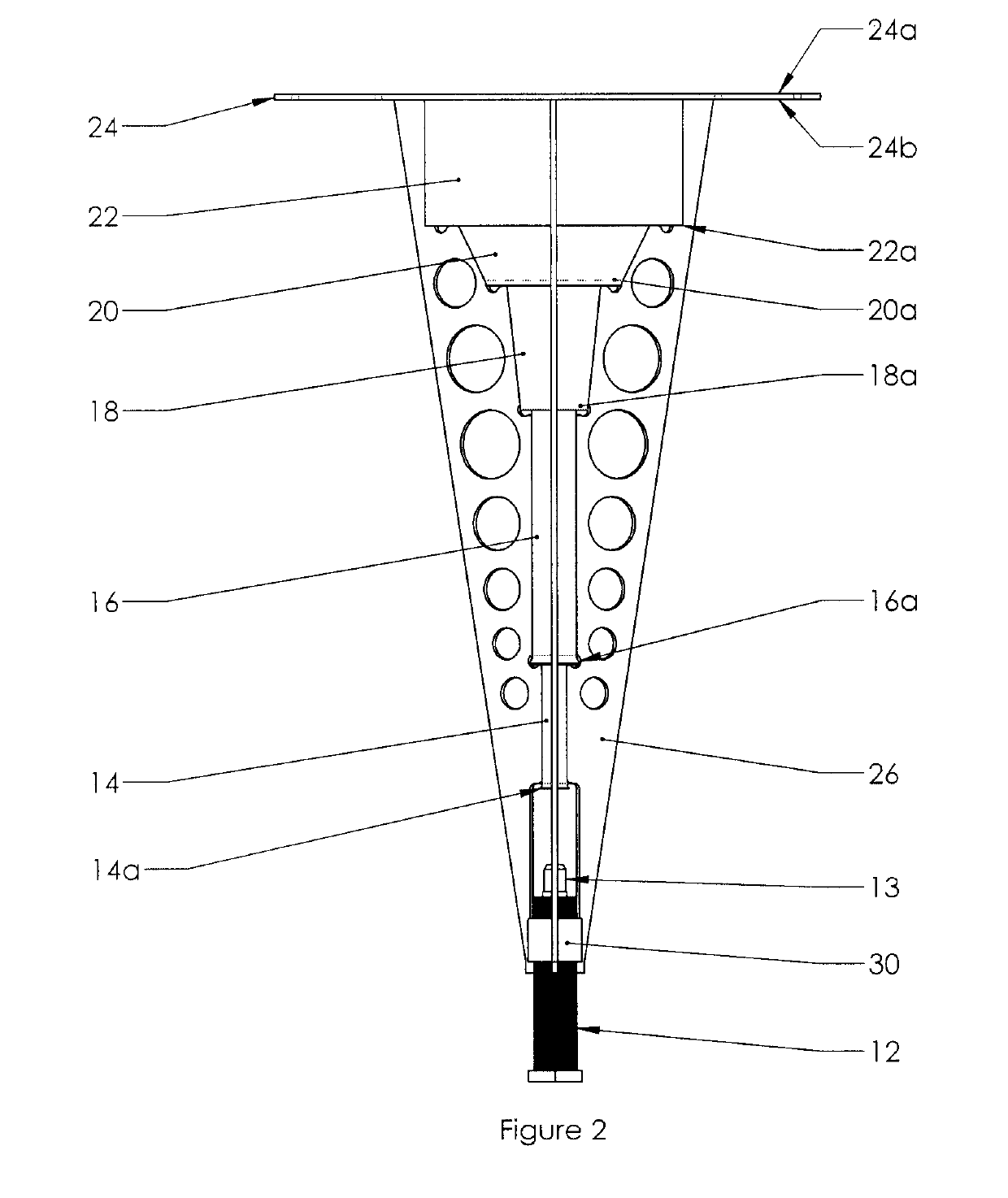
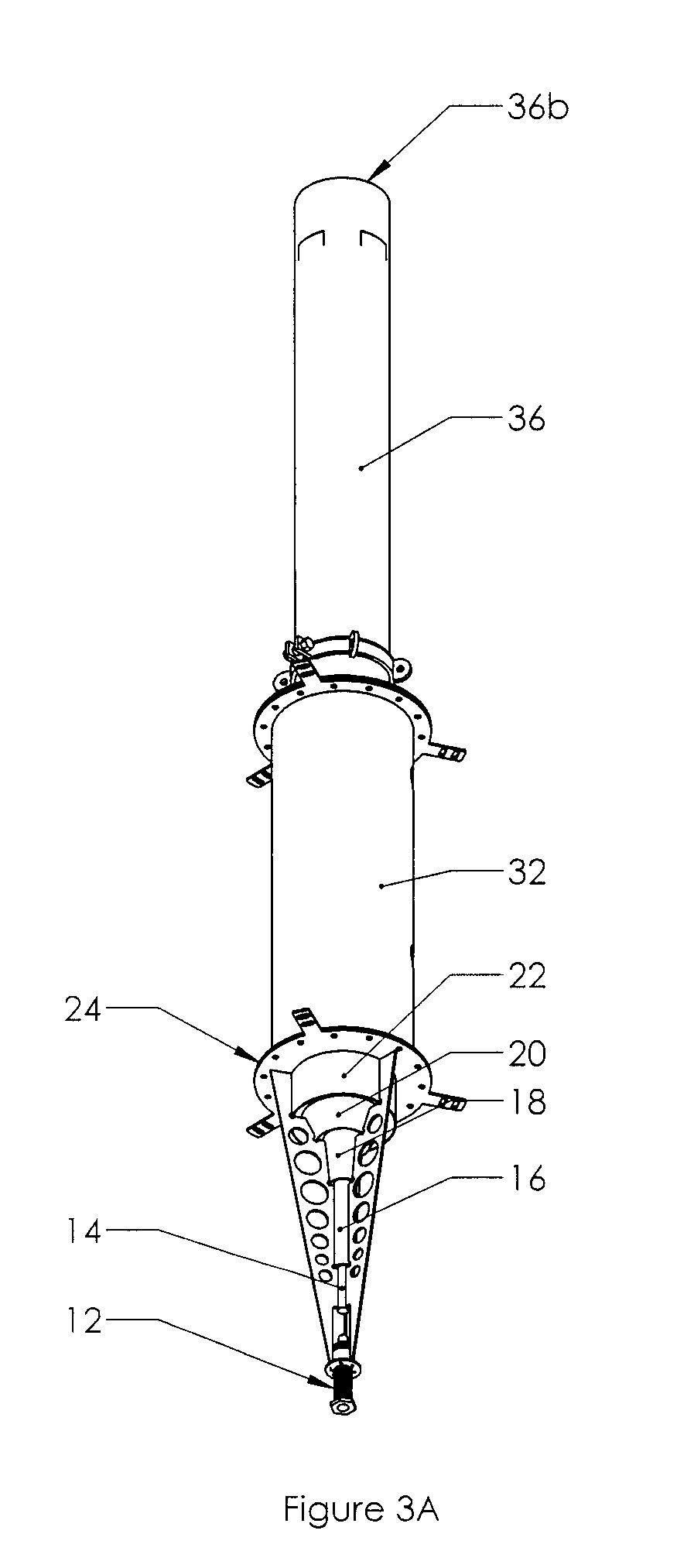
This patent is about a method for improving the way fuel is incinerated by using a multi-stage fuel-air mixing device. This device has several vertical tubes stacked on top of each other, with each tube having a bigger inlet than an outlet, allowing more air to be entrained. When fuel is injected into this device, it mixes with the air and is designed to flow into a combustor with enough retention time to ensure complete combustion. This method creates a fuel-air mixture that is ready to be ignited in the combustor.

Problems solved by technology

Flammable hydrocarbons are generally used as energy sources but some situations may require their destruction, for instance in the event of a production surplus or an unexpected shutdown of equipment.
Some flammable hydrocarbons are byproducts of natural or industrial processes where the source cannot be stopped and / or be easily controlled, and cannot be stored for a later use.
Thus, if the methane gas contained in a gas stream coming out of a landfill site cannot be readily used or stored, it should be destroyed by combustion in a gas flare.

Method used


Image

  • Incinerating system
  • Incinerating system
  • Incinerating system

Examples


Embodiment Construction

[0036]Unless defined otherwise, all technical and scientific terms used herein have the same meaning as commonly understood by one of ordinary skill in the art to which this invention belongs.

[0037]The term “fuel” as used herein includes waste gases and liquids occurring at gas and oil drilling sites or waste process gases and liquids from chemical and petrochemical application. Non limiting examples of waste gases are gases comprising methane, propane, butane and pentane and mixture thereof.

[0038]The expression “substantially complete combustion” as used herein refers to the combustion wherein at least 80% of the fuel has been combusted.

[0039]The term “combustion region” as used herein refers to at least ¼ of the length of the combustor.

[0040]As used herein, the term “about” refers to approximately a + / −10% variation from a given value. It is to be understood that such a variation is always included in any given value provided herein, whether or not it is specifically referred to.

[...


PUM


Abstract

The present invention provides a fuel incinerating system comprising a fuel injector, a multi-stage fuel-air mixing device comprising a plurality of fuel intake tubes stacked vertically and configured to provide annular gaps between one or more of the vertically stacked fuel intake tubes to entrain ambient air to form a fuel-air mixture; and a combustor in communication with the fuel-air mixing device and defining a combustion chamber and in communication with an ignition source. The combustor is configured to impede flow of the fuel-air mixture through the combustion chamber to achieve a desired retention time of the fuel-air mixture within the combustion chamber to achieve substantially complete combustions of the fuel.

Description

FIELD[0001]The invention relates generally to incinerator and flare systems for combustion of hydrocarbons, such as waste gases and liquids occurring at gas or oil drilling sites, or waste process gases and liquids from various chemical and petrochemical applications.BACKGROUND[0002]Flammable hydrocarbons are generally used as energy sources but some situations may require their destruction, for instance in the event of a production surplus or an unexpected shutdown of equipment. Some flammable hydrocarbons are byproducts of natural or industrial processes where the source cannot be stopped and / or be easily controlled, and cannot be stored for a later use.[0003]One example of source of a flammable gas that cannot be stopped and / or be easily controlled is a landfill site. In a landfill site, organic matter contained in the waste slowly decays over time using a natural process, generating a gas stream containing methane (CH4). Methane is a flammable gas and is mixed with other flammab...

Claims


Application Information

Patent Timeline
Patent Type & Authority Applications(United States)
IPC IPC(8): F23C5/08
CPCF23C5/08F23C5/02F23J15/003F23C7/008F23D14/02F23G7/08F23C2900/06041F23C7/00F23D14/08
Inventor MRAVCAK, VLADIMIRNEUMAN, DALE
Owner ATLANTIS RES LABS INC
Learn More