Device and method for forming a three-dimensional object from a liquid polymer

a liquid polymer and three-dimensional object technology, applied in the direction of metal-working equipment, manufacturing tools, additive manufacturing, etc., can solve the problems of not providing a sufficiently high quality of built objects, method does not allow continuous exposure and movement of formed objects, and object building is rather slow

Inactive Publication Date: 2019-04-18
KHALIP OLEG YUREVICH
View PDF4 Cites 20 Cited by
  • Summary
  • Abstract
  • Description
  • Claims
  • Application Information

AI Technical Summary

Benefits of technology

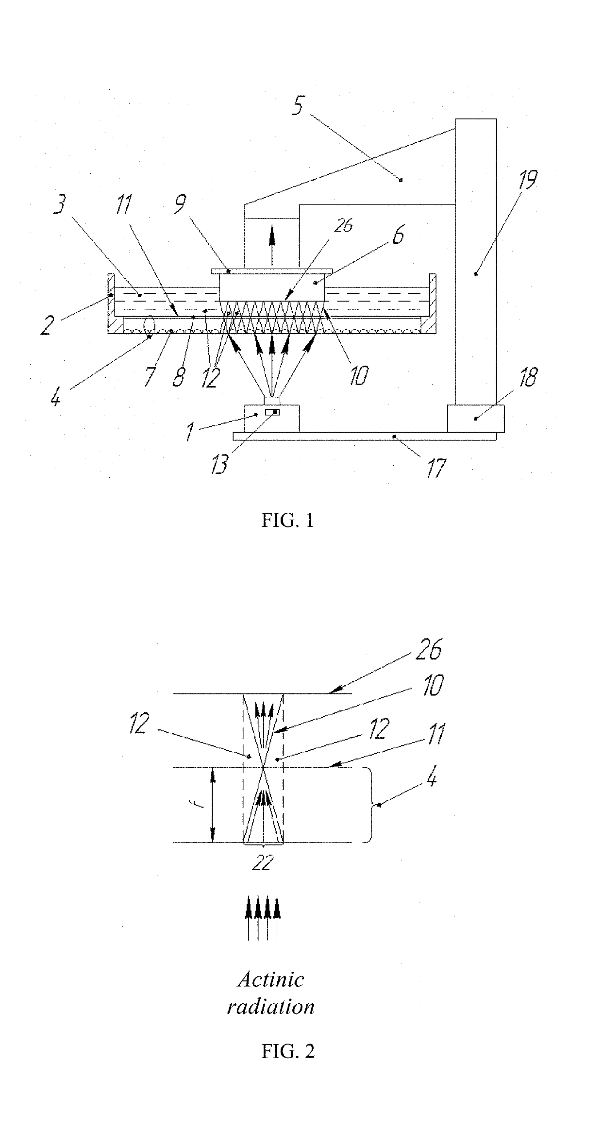
[0067]In the case when at least one of the sources of actinic radiation is a source of coherent radiation, it becomes possible to form a holographic field in the region of object construction in the form of a spatial interference pattern with a given spatial distribution of the specific radiative intensity, which allows to save part of the photopolymer in the volume of the formation zone that is not exposed, providing a permanent presence of a liquid photopolymer in the construction area.

Problems solved by technology

These two effects prevent the liquid photopolymer from flowing smoothly into the exposure zone of the cross-section of the forming object and do not allow the object forming process to be continuously carried out, therefore, one section layer is exposed during the manufacturing process, then the exposure is interrupted, the object is moved along the vertical axis by the layer thickness.
Disadvantages of this known method is that the object building is rather slow and, moreover, it does not provide a sufficiently high quality of the built objects.
This known method does not allow for the exposure and movement of the formed object to be performed continuously, the object is formed layer by layer with pauses between the radiation exposures.
Disadvantages of the known method is that it does not provide a sufficiently high rate of object formation and does not provide a sufficiently high quality of the objects to be formed.
This known method does not allow for the exposure and movement of the formed object continuously, the object is formed layer by layer with pauses in the exposure.
Disadvantages of this known method is that it does not provide a sufficiently high rate of object formation and, moreover, does not provide a sufficiently high quality of the formed objects.
This negatively affects the quality of manufactured objects, because the inhibitor accumulates and degrades the characteristics of the photopolymer, which remains in the container after the manufacturing of one or more objects.
In addition, the quality of the formed object is affected by the fact that the properties of the photopolymer immediately in the formation zone, i.e., in the mobile, partially inhibited zone, are changed under the action of the polymerization inhibitor, and two opposite processes are simultaneously occurred during the formation of the object: inhibition and polymerization, therefore the polymerization rate potential cannot be fully realized.
The known method does not allow using photopolymers with different types of polymerization without additional techniques.
The disadvantages of this known device is that it does not provide a sufficiently high rate of object formation and, moreover, does not provide a sufficiently high quality of the object to be formed.
This negatively affects the quality of the manufactured object, as the inhibitor accumulates and degrades the characteristics of the photopolymer, which remains in the container after the manufacture of one or more objects.
In addition, the quality of the formed object is affected by the fact that the properties of the photopolymer immediately in the formation zone, i.e., in the mobile, partially inhibited zone, are changed under the action of the polymerization inhibitor, and two opposite processes are simultaneously realized during the formation of the object: inhibition and polymerization, i.e., the polymerization rate potential cannot be fully realized.

Method used


Image

  • Device and method for forming a three-dimensional object from a liquid polymer
  • Device and method for forming a three-dimensional object from a liquid polymer
  • Device and method for forming a three-dimensional object from a liquid polymer

Examples


example 1

[0209]Test object having a cruciform cross-section, twisted into a spiral at half-length, with a structural surface, 30×30×60 mm size, wall thickness of 1.2 mm (see. FIG. 20) made of transparent acrylic photopoyler from the company “Fun To Do”, Vossenkoog 2-4 1822BG Alkmaar, Netherlands

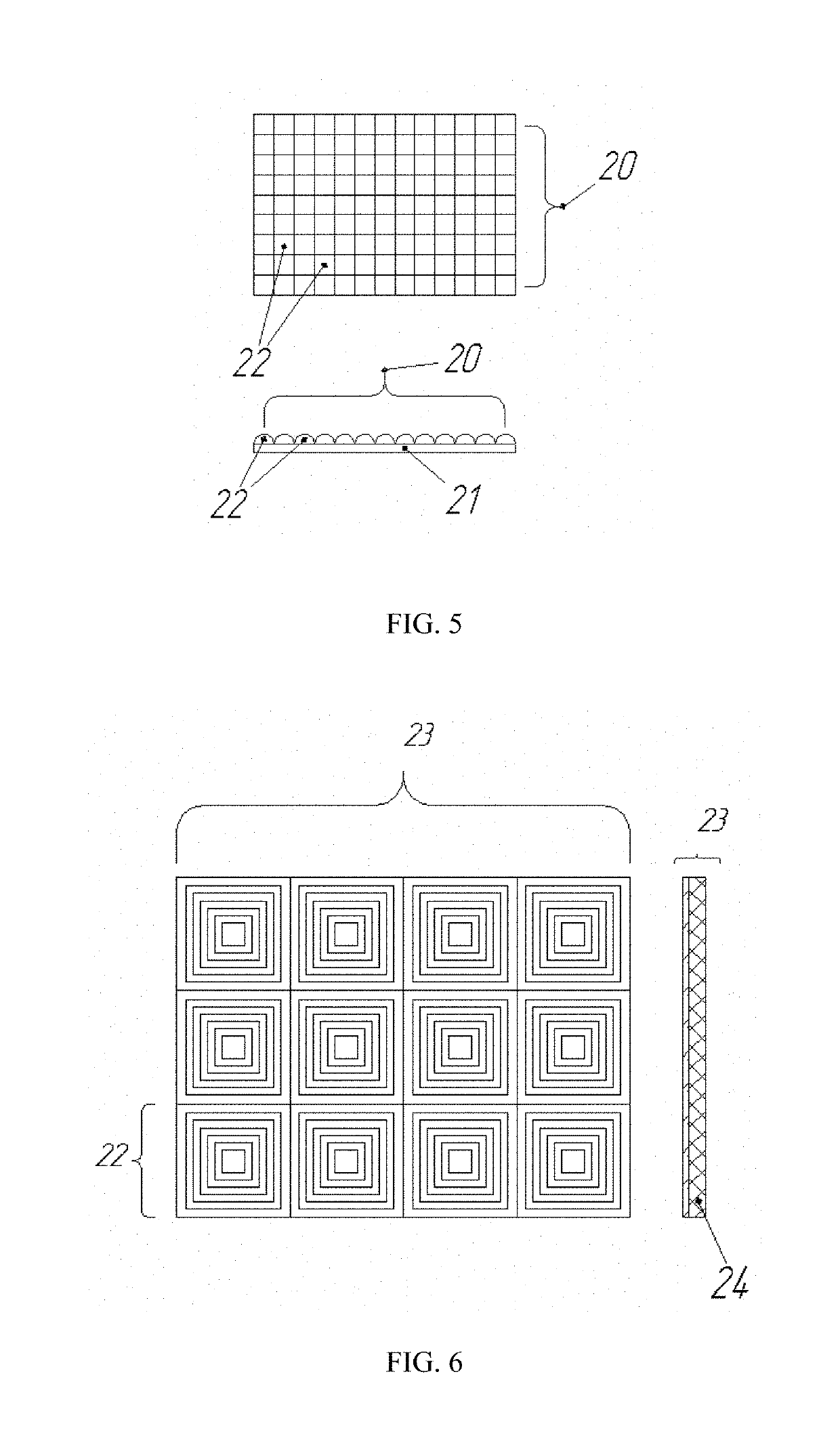
[0210]The optical interface design was used, which is a reservoir for a photopolymer made of polyethylene, the bottom of which is made in the form of a composite structure similar to that shown in FIG. 7, where: as the material of the element intended for contact with the photopolymer, a polypropylene film having a thickness of 20 μm was used. The wavefront converter was an array of hexagonal microlenses 80 μm in size with a focal length of 40 μm, based on a thickness of 300 μm, made of PMMA (FIG. 17). Molds for casting such lenses on standard equipment are available from the company “NIL Technology” Ar Diplomvej 381 DK-2800 Kongens Lyngby, Denmark.

[0211]The exposition was carried out by a multimedia ...

example 2

[0216]A test object having a square cross-section of 6×6×50 mm (see FIG. 21) made of acrylic photopolymer from the company “Fun To Do” Vossenkoog 2-4 1822BG Alkmaar, The Netherlands.

[0217]We used an optical interface design, which is a reservoir for a fluoropolymer photopolymer, whose bottom is made in the form of a composite structure (FIG. 7), where:[0218]as the material of the element intended for contact with the photopolymer, a polyethylene film with a thickness of 10 μm was used;[0219]as a wavefront converter, a thin hologram was used on a 30 μm film carrier, representing an array of hologram lenses of square shape with dimensions of an elementary microlens of 25×25 μm and a focal length of 30 μm (see FIG. 18), such holograms are manufactured by Holoptica 425 Old Country Road, Suite A & B, Belmont CA 94002, USA;[0220]As a cooling unit of the optical interface, a flat reservoir 4 mm thick was used, filled with a coolant, which used water, the coolant circulation was not carried...

example 3

[0227]A test object having a cross-section of 10×10×80 mm in dimensions with a wall thickness of 0.8 mm, with a smooth surface (see FIG. 22) made from a photopolymer containing a white pigment, from the company “Fun To Do” Vossenkoog 2-4 1822BG Alkmaar, The Netherlands.

[0228]We used an optical interface design, which is a reservoir for a fluoropolymer photopolymer, whose bottom is made in the form of a composite structure (FIG. 7), where:[0229]as a material of the element intended for contact with the photopolymer, a film of oriented polyethylene with a thickness of 8 μm was used;[0230]a hologram of the type of cineforms on a 30 μm film carrier was used as the wave front converter, which is a array of hexagonal holograms of a Fresnel hologram with dimensions of an elementary microlens of 35 μm and a focal length of 40 μm (see FIG. 19), such holograms are manufactured by Holoptica “425 Old Country Road, Suite A & B, Belmont Calif. 94002, USA;[0231]as a cooling unit of the optical int...


PUM

PropertyMeasurementUnit
speedaaaaaaaaaa
sizesaaaaaaaaaa
sizesaaaaaaaaaa

Abstract

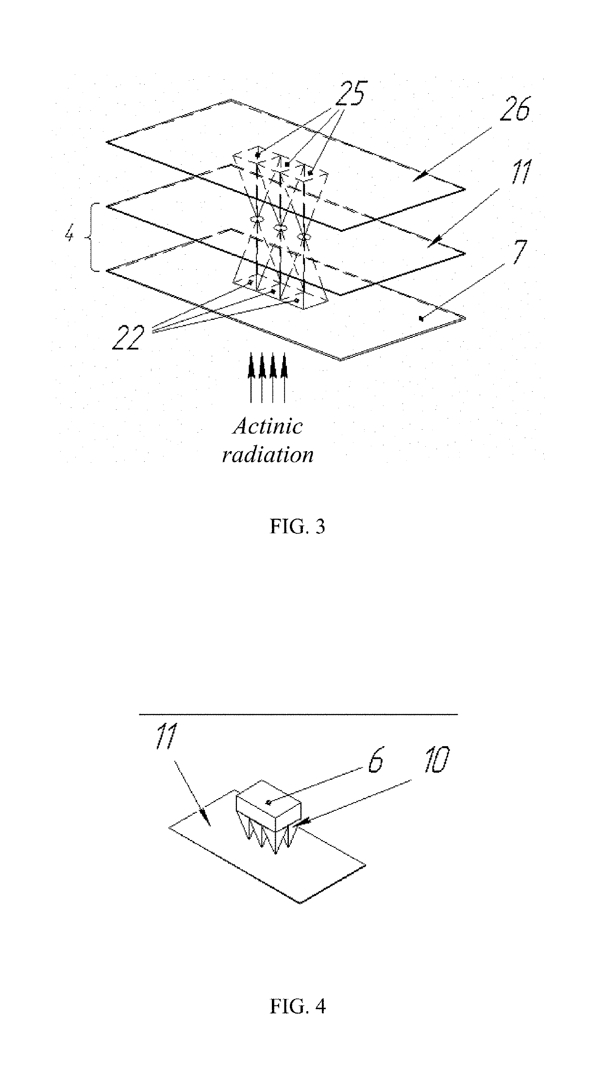
The invention relates to the field of producing polymer objects and concerns a method and a device for forming a three-dimensional object from a liquid photopolymer. The present method includes exposing elementary cross sections by actinic radiation, moving an object along a construction axis, and forming the object from a fluid zone of a border zone of the photopolymer. To provide fluidity of the border zone, the wave front of the radiation is converted so that the specific power of the radiation on the exposed regions has a gradient along the construction axis. A device for forming a three-dimensional object comprises a source of actinic radiation, a mechanism for moving an object along a construction axis, and a vessel for accommodating a photopolymer, which is provided with an optical interface window being in the form of a converter for converting the wave front of the actinic radiation.

Description

TECHNICAL FIELD[0001]The invention relates to the construction of three-dimensional objects / objects by curing the liquid photopolymer using actinic radiation.BACKGROUND OF THE INVENTION[0002]A method for forming a three-dimensional object from a liquid photopolymer by curing with actinic radiation is well known, see, for example, U.S. Pat. No. 7,438,846, application number US 20070063389 filed Mar. 22, 2007, published Oct. 21, 2008, MP B2813 7 / 36, B29C 33 / 68, B29C 35 / 04; it includes the object illumination by actinic radiation using a projection system, the exposure of the photopolymer with a set of projected cross-sections of the object, the movement of the object along the axis of construction and building up three-dimensional objects in layers from “light-hardening” photopolymers. In this case, the building zone is limited by the projector window—the optical interface, and the elastic film is used as the material bordering the photopolymer.[0003]During exposure to actinic radiati...

Claims


Application Information

Patent Timeline
Patent Type & Authority Applications(United States)
IPC IPC(8): B29C64/268B29C64/135B33Y10/00B33Y30/00
CPCB29C64/268B33Y30/00B33Y10/00B29C64/135
Inventor KHALIP, OLEG YUREVICH
Owner KHALIP OLEG YUREVICH
Why Eureka
Try Eureka