
Light emitting diode and light emitting display device including the same

a light emitting display device and light emitting diode technology, applied in static indicating devices, solid-state devices, instruments, etc., can solve the problems of reducing the light emission efficiency of the oled, increasing the power consumption, and very serious problems of the oled using a quantum dot having a very low homo energy level

Active Publication Date: 2019-04-18
LG DISPLAY CO LTD
View PDF1 Cites 5 Cited by
  • Summary
  • Abstract
  • Description
  • Claims
  • Application Information

AI Technical Summary

Benefits of technology

The present invention is about a new light emitting diode (LED) and a light emitting apparatus that solves problems with existing LEDs. It has advantages not previously available.

Problems solved by technology

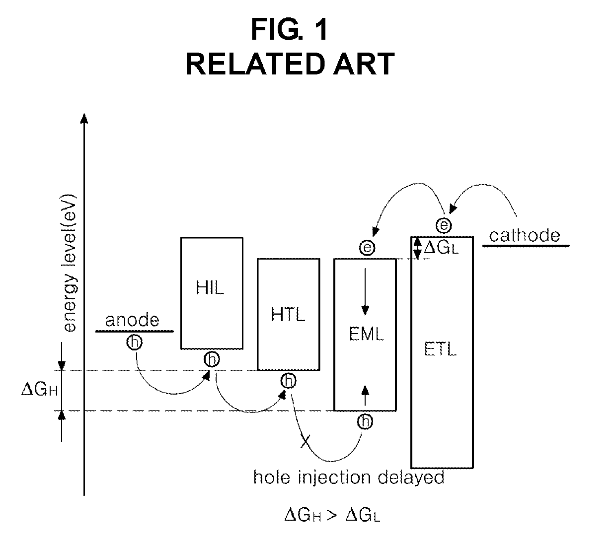
This problem is very serious to an OLED using a quantum dot having a very low HOMO energy level as a light emitting material.
Accordingly, a light emission efficiency of the OLED is reduced, and a high driving voltage is required to realize a desired light emission thus an increase of a power consumption is caused.

Method used


Image

  • Light emitting diode and light emitting display device including the same
  • Light emitting diode and light emitting display device including the same
  • Light emitting diode and light emitting display device including the same

Examples


synthesis example 1

:Cu

[0138]A mixture of Zinc acetate(Zn(CH3COO)2), CuSO4, and MnCl2 was mixed into an aqueous Na2S solution to synthesize ZnS:Mn:Cu nano particles, where a dosage amount of Mn and Cu was about 0.1 wt % to about 1.0 wt % with respect to ZnS. An aqueous solution of Zinc acetate (1M), CuSO4 and MnCl2 (0.1M) was added into an autoclaved D.I. water at a temperature of 70° C. While an inside ambient condition was maintained with N2 being supplied through a condenser, a stirring was intensely conducted using a magnetic stirrer. Then, an 1M mercaptoethanol was added into the mixture and a stirring was conducted for 20 minutes. Finally, Na2S was added into the reaction mixture such that Zn:S has a mol ratio of 1:1, and a ZnS:Mn:Cu precipitate was produced. The reaction mixture was refluxed for one hour under the same condition. The produced precipitate was cleaned repeatedly with a D.I. water and was centrifuged (e.g., at 15,000 rpm) for 20 minutes. A final cleaning process was conducted using...

synthesis example 2

:Ni

[0139]Through the processes of the synthesis example 1 that was modified to use Ni(NO3)2 as a nickel precursor replacing CuSO4 as a copper precursor, ZnS:Mn:Ni nano particles were synthesized.

synthesis example 3

:Eu

[0140]Through the processes of the synthesis example 1 that was modified to use EuCl3 as an europium precursor replacing CuSO4 as a copper precursor, ZnS:Mn:Eu nano particles were synthesized.


PUM


Abstract

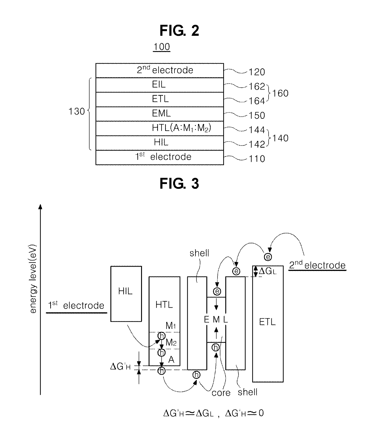
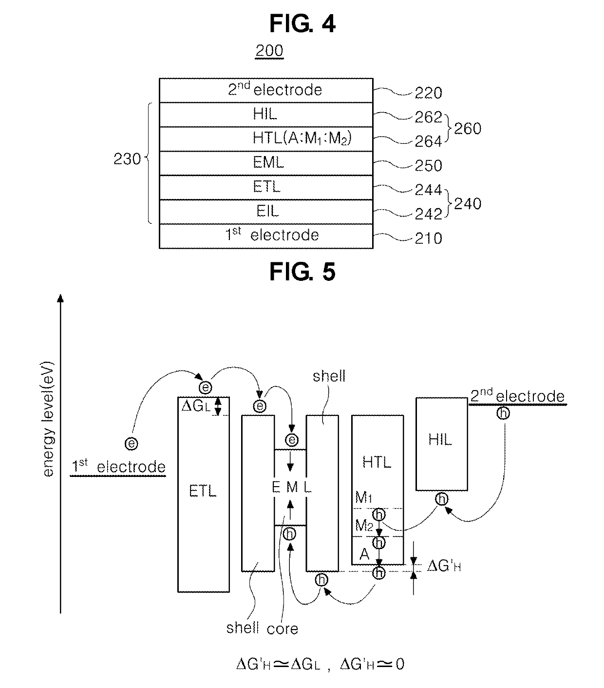
A light emitting diode and a light emitting display device are disclosed. The light emitting diode includes a first electrode and a second electrode facing each other; and a hole transporting layer between the first electrode and the second electrode, wherein the hole transporting layer includes an inorganic compound of a chemical formula 1, A:M1:M2, where the A is a semiconductor nano particle or a nano inorganic particle selected from a metal oxide group, and the M1 and M2 are different from each other and represent metal positive ions which the A is doped with.

Description

CROSS-REFERENCE TO RELATED APPLICATIONS[0001]This application claims priority benefit under 35 U.S.C. § 119(a) of Korean Patent Application No. 10-2017-0133872 filed in the Republic of Korea on Oct. 16, 2017, which is hereby incorporated by reference in its entirety.BACKGROUND OF THE INVENTIONField of the Invention[0002]The present invention relates to a light emitting diode, and more particularly, to a light emitting diode and a light emitting apparatus using the same in which a charge can be injected into a light emitting layer.Discussion of the Related Art[0003]Recently, as the technology for display processing and display of a large amount of information have rapidly advanced, various flat display devices have been developed. Among the flat display devices, an organic light emitting diode (OLED) display device and a quantum dot light emitting diode (QLED) display device are able to be thin and have a low power consumption. Thus, these flat display devices have been used as next ...

Claims


Application Information

Patent Timeline
IPC IPC(8): H01L51/50H01L51/52H01L27/32G09G3/3225
CPCH01L51/5064H01L51/5004H01L51/5072H01L51/5092H01L51/5096H01L51/5221H01L51/5206H01L51/5237H01L51/502H01L27/3246G09G3/3225G09G2310/0264H10K59/12H10K50/115H10K50/155H10K2102/101H10K2102/00H10K2102/103H10K50/156H10K50/15H10K2102/331H01L33/02H01L33/36H10K50/11H10K50/16H10K50/18H10K50/81H10K50/82H10K50/84H10K50/171H10K59/122H10K2101/40
Inventor LEE, TAE-YANGCHOI, SEUL-GIHYUNG, MIN-SURK
Owner LG DISPLAY CO LTD
Learn More