Digitally assisted feedback loop for duty-cycle correction in an injection-locked pll

a digital assisted feedback and duty-cycle correction technology, applied in pulse automatic control, pulse manipulation, pulse technique, etc., can solve the problems of exacerbated jitter, inability to scale well, and inability to apply to ring oscillators in deep sub 50 nm technology,

Active Publication Date: 2019-04-18
ORACLE INT CORP
View PDF0 Cites 4 Cited by
  • Summary
  • Abstract
  • Description
  • Claims
  • Application Information

AI Technical Summary

Problems solved by technology

Conventional inductor-capacitor-based clocking sources have not been scaling well as semiconductor integration densities continue to increase.
However, compared to their LC-based counterparts, ring-based PLLs inherently have more jitter, which is exacerbated as the technology scales further.
Moreover, while the injection-locking technique is widely used in LC oscillators, its application to ring oscillators in deep sub 50 nm technology has been challenging due to high noise, frequency drift, and supply sensitivity in ring oscillators.
A particular problem arises in situations where injection locking is used to suppress phase errors while frequency correction is taking place.
In this case, the injection locking will tend to mask the frequency errors while suppressing the phase errors.
This makes it hard to correct frequency errors in the PLL, which can significantly degrade the quality of the resulting clock signal.

Method used


Image

  • Digitally assisted feedback loop for duty-cycle correction in an injection-locked pll
  • Digitally assisted feedback loop for duty-cycle correction in an injection-locked pll
  • Digitally assisted feedback loop for duty-cycle correction in an injection-locked pll

Examples


Embodiment Construction

[0030]The following description is presented to enable any person skilled in the art to make and use the present embodiments, and is provided in the context of a particular application and its requirements. Various modifications to the disclosed embodiments will be readily apparent to those skilled in the art, and the general principles defined herein may be applied to other embodiments and applications without departing from the spirit and scope of the present embodiments. Thus, the present embodiments are not limited to the embodiments shown, but are to be accorded the widest scope consistent with the principles and features disclosed herein.

[0031]The data structures and code described in this detailed description are typically stored on a computer-readable storage medium, which may be any device or medium that can store code and / or data for use by a computer system. The computer-readable storage medium includes, but is not limited to, volatile memory, non-volatile memory, magneti...


PUM


Abstract

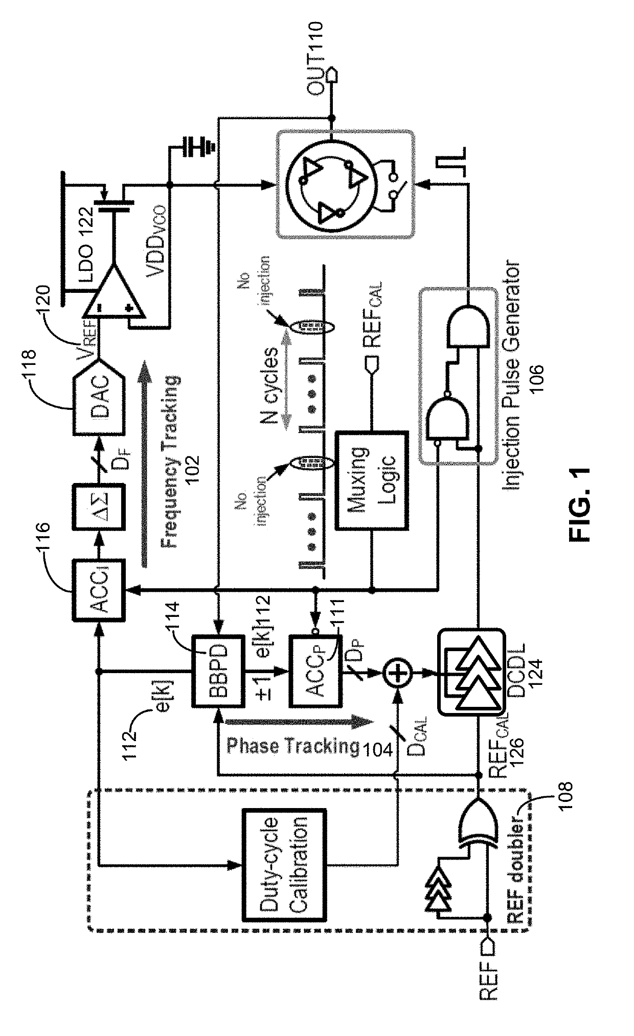
We disclose a system, which performs a duty-cycle correction operation for an injection-locked phase-locked loop (PLL). The system first obtains a pattern of positive and negative error pulses at rising and falling edges of a reference clock signal for the injection-locked PLL, wherein the pattern specifies deviations of the reference clock signal from a 50% duty cycle. The system multiplies the pattern of positive and negative error pulses by a duty-cycle distortion (DCD) template, which specifies a sign of a duty-cycle error for the reference clock signal, to calculate duty-cycle distortion values. The system then accumulates the duty-cycle distortion values to produce a duty-cycle-error amplitude. Next, the system multiplies the duty-cycle-error amplitude by the DCD template to produce a duty-cycle correction signal. Finally, the system uses the duty-cycle correction signal to compensate for timing errors in the injection-locked PLL, which are caused by duty-cycle variations in the reference clock signal.

Description

RELATED APPLICATION[0001]This application claims priority under 35 U.S.C. § 119 to U.S. Provisional Application No. 62 / 571,520, entitled “Injection-Locking PLL with Frequency Drift Tracking and Duty-Cycle Distortion Cancellation” by the same inventors as the instant application, filed on 12 Oct. 2017, the contents of which are incorporated herein by reference.BACKGROUNDField[0002]The disclosed embodiments generally relate to the design of injection-locked phase-locked loops (PLLs). More specifically, the disclosed embodiments relate to the design of a digitally assisted feedback loop to facilitate duty-cycle correction in an injection-locked PLL.Related Art[0003]Conventional inductor-capacitor-based clocking sources have not been scaling well as semiconductor integration densities continue to increase. This has caused ring-based PLLs to become more popular, especially in area-constrained designs associated with the latest technology nodes. However, compared to their LC-based counter...

Claims


Application Information

Patent Timeline
Patent Type & Authority Applications(United States)
IPC IPC(8): H03L7/081H03L7/197H03L7/099
CPCH03L7/0814H03L7/197H03L7/0996H03K3/0315H03K5/1565H03L7/081H03L7/0995H03L7/24H03L2207/50H03L7/087H03L7/0998H03L7/1976
Inventor SHU, GUANGHUALIU, FRANKIE Y.YANG, SUWENSHEHADEH, ZIAD SALEHCHANG, ERIC Y.
Owner ORACLE INT CORP
Why Eureka
Try Eureka