Unlock instant, AI-driven research and patent intelligence for your innovation.

Evaporative fuel processing device and fluid processing device

a technology of evaporative fuel and processing device, which is applied in the direction of combustion-air/fuel-air treatment, machine/engine, fuel air intake, etc., can solve the problems of negative pressure generation, inability to purge evaporative fuel, and absorbed by activated carbon, so as to reduce the number of components, increase the flow rate of fluid flowing through the narrowing down part, and reduce the effect of negative pressur

Active Publication Date: 2019-05-02
HONDA MOTOR CO LTD
View PDF0 Cites 2 Cited by
  • Summary
  • Abstract
  • Description
  • Claims
  • Application Information

AI Technical Summary

Benefits of technology

The present invention relates to an evaporative fuel processing device for vehicles. The device has a purge pump that can detach from the vehicle's canister and discharge evaporative fuel into the intake passage of the engine. The device has a cylindrical body with a connection part that allows fluid to flow through the device. The device also includes a fragile part that improves its manufacturability. The device can increase the negative pressure in the pump flow passage and allow the purge pump to draw more evaporative fuel. The device can also reduce the number of components and improve its manufacturability. The device has a narrowing down part that generates negative pressure and allows the purge pump to draw fluid from the canister and discharge it into the intake passage. Overall, the evaporative fuel processing device improves the performance and efficiency of vehicles' evaporative fuel processing.

Problems solved by technology

However, in the case where the intake pipe is provided with a compressor of a supercharger, a part downstream of this compressor becomes positive pressure during supercharging, and therefore it is not possible to purge evaporative fuel, absorbed by the activated carbon, by use of negative pressure.
Meanwhile, in the evaporative fuel processing device described above, the purge pump is secured on an intake pipe with screws and bolts etc., but they are sometimes detached or broken unintentionally due to various reasons such as vibration of the vehicle and failing to fasten them during maintenance.
However, in the existing evaporative fuel processing device, the air flows in the purge pump from the downstream side of the compressor toward the atmosphere even when the purge pump is detached from the intake pipe, and therefore negative pressure is generated and the evaporative fuel absorbed by the activated carbon might flow out to the atmosphere.

Method used


Image

  • Evaporative fuel processing device and fluid processing device
  • Evaporative fuel processing device and fluid processing device
  • Evaporative fuel processing device and fluid processing device

Examples


first embodiment

[0038]Hereinbelow, a first embodiment of the present invention is described with reference to the drawings.

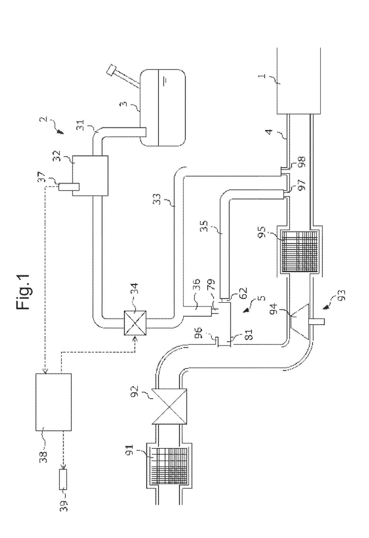
[0039]FIG. 1 is a diagram schematically illustrating the configuration of an evaporative fuel processing device 2 according to this embodiment and that of an intake system of an internal combustion engine (hereinafter simply referred to as an “engine”) 1 that employs this evaporative fuel processing device 2.

[0040]An intake pipe 4 designed to feed the air into each cylinder (not illustrated) of the engine 1 is provided with, from the upstream side to the downstream side: an air cleaner 91 which is configured to remove foreign substances in the air; an airflow meter 92 which is configured to generate a signal according to the flow rate of the air to be introduced into each cylinder through the intake pipe 4; a compressor 94 of a supercharger 93 which is configured to compress intake air using exhaust energy of the engine 1; and an intercooler 95 which is configured to cool intak...

second embodiment

[0074]Next, a second embodiment of the present invention is described with reference to the drawings. An evaporative fuel processing device according to this embodiment differs from the evaporative fuel processing device 2 according to the first embodiment in the configuration of a purge pump. Note that, in the following description, the same constituents as those of the first embodiment are given the same reference numerals and the description thereof is omitted.

[0075]FIG. 8 is a sectional view of a purge pump 5A used in an evaporative fuel processing device 2A according to this embodiment. The first embodiment illustrates the case where the coupling part 96 formed integrally with the intake pipe 4 and the purge pump 5 are separate members. On the other hand, the purge pump 5A according to this embodiment differs from the purge pump 5 according to the first embodiment in that it includes a coupling part 96A, formed integrally with the intake pipe 4, as its component and exerts its ...

third embodiment

[0082]Next, a third embodiment of the present invention is described with reference to the drawings. An evaporative fuel processing device according to this embodiment differs from the evaporative fuel processing device 2 according to the first embodiment in the configuration of a purge pump. Note that, in the following description, the same constituents as those of the first embodiment are given the same reference numerals and the description thereof is omitted.

[0083]FIG. 9 is a sectional view of a purge pimp 5B used in an evaporative fuel processing device 2B according to this embodiment. A main body 51B of the purge pump 5B is in the form of a cylinder extending along the axis line O, and the pump flow passage 52 extending along the axis line O is formed inside the main body. The main body 51B of the purge pump 5B is composed of: an upstream part 6B which constitutes the upstream side in the flow direction F1; and a discharge pipe 81B which constitutes the downstream side in the ...


PUM


Abstract

A pump flow passage 52 which extends in a flow direction F1 and through which fluids introduced through first and second inlet pipe 62, 79 flow is disposed inside a main body 51 of a purge pump 5 of an evaporative fuel processing device, a venturi 53 which decreases in diameter toward downstream is formed in the pump flow passage 52 at a position downstream of the first inlet pipe 62 in the flow direction F1, the main body 51 has an upstream-side member 6 in which the first inlet pipe 62 is disposed, and a downstream-side member 8 in which a discharge pipe 81 is disposed, and connection faces 74, 87 of the upstream-side member 6 and the downstream-side member 8 are disposed upstream of the smallest diameter part 55, at which the inner diameter of the venturi 53 is the smallest, in the flow direction F1.

Description

CROSS-REFERENCE TO RELATED APPLICATION[0001]This application claims priority of Japanese Patent Application No. 2017-212629 filed in Japan on Nov. 2, 2017, the entire contents of which are incorporated herein by reference.TECHNICAL FIELD[0002]The present invention relates to an evaporative fuel processing device and a fluid processing device.BACKGROUND OF THE INVENTION[0003]A vehicle with a fuel tank is equipped with an evaporative fuel processing device which is configured to process evaporative fuel generated in this fuel tank. An existing evaporative fuel processing device makes evaporative fuel, generated in the fuel tank, absorbed by an activated carbon in a canister, purges the evaporative fuel, absorbed by the activated carbon, with the fresh air by use of negative pressure generated in an intake pipe, and introduce it into the intake pipe to combust it in an engine. However, in the case where the intake pipe is provided with a compressor of a supercharger, a part downstream ...

Claims


Application Information

Patent Timeline
IPC IPC(8): F02M25/08F02M35/10F04F5/20
CPCF02M25/089F02M25/0854F02M35/10222F04F5/20
Inventor KAWANISHI, HIROSHISAIGA, JUNJI
Owner HONDA MOTOR CO LTD