Electrical energy storage cell with integrated bridging device

Active Publication Date: 2019-05-02
FRAUNHOFER GESELLSCHAFT ZUR FOERDERUNG DER ANGEWANDTEN FORSCHUNG EV
View PDF4 Cites 0 Cited by
  • Summary
  • Abstract
  • Description
  • Claims
  • Application Information

AI Technical Summary

Benefits of technology

The patent proposes an energy storage cell with a bridging device that can be triggered by an electrical pulse. The bridging device acts between two terminals of the cell, which reduces the risk of false triggering and ensures reliable triggering even at low energy levels. The cell can also have a retaining wire and a reactive layer or element to further reduce the risk of triggering. The proposed embodiment has a low residual resistance and allows for thermal dissipation of power loss. The trigger input can also be used for cell diagnosis functions. Overall, the patent presents a reliable and cost-effective solution for triggering energy storage cells.

Problems solved by technology

In the event of high-impedance failure of a destroyed storage cell, the high charging current flows through the two semiconductor components, which break down on account of the resultant high increase in temperature and thus short circuit the storage cell irreversibly with low impedance.
A passive bridging device of this kind, however, is triggered only if the accumulator cell is already heavily degraded.
Premature triggering, for example to prevent high power losses, is not possible.
These materials, however, tend towards heavy creepage already at the upper end of the temperature range of many storage cells, for example conventional Li-ion cells (60 to 80° C.
), whereby the risk of undesirable triggering of the bridging element increases with time.
It is thus impossible to achieve long-term stability.
A plate of 5×5×1 mm3 made of LD polyethylene, for example in order to heat up from room temperature to a softening point of 100° C., thus requires an energy quantity of approximately 3.5 J. Furthermore, in the case of this bridging element there is also the risk that residues of the insulation material will remain in the contact region, whereby the residual resistance in the event that the bridging element is triggered can present very high parameter fluctuations.
A primary problem of the previously available solutions is constituted by the overall cost to produce a battery system formed of a number of storage cells, with the assembly costs in particular for the mounting of the bridging devices on the individual storage cells contributing towards this.
This assembly effort can also increase the susceptibility to failure of the battery system.

Method used


Image

  • Electrical energy storage cell with integrated bridging device
  • Electrical energy storage cell with integrated bridging device

Examples


Embodiment Construction

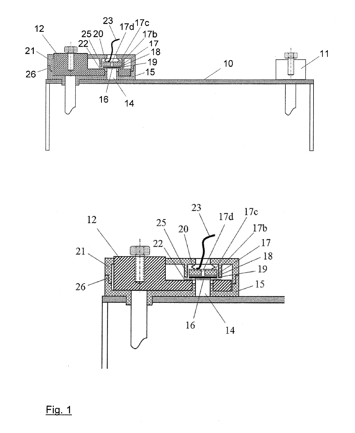
[0027]FIG. 1 shows, in the upper sub-image a), an exemplary embodiment of the proposed energy storage cell with the integrated bridging device in cross-section. The energy storage cell, as is known, in this case has the two terminals 11, 12, which protrude from the housing 10. The housing 10 is electrically conductive at least on its upper side, wherein the second battery terminal 11 is electrically conductively connected to the housing and the first battery terminal 12 is insulated from the housing 10. The insulated battery terminal 12 comprises a recess with an aperture. A contact part 14 is placed in said aperture as electrical conductor of the bridging device, which is electrically conductively connected to the housing 10 and thus also to the non-insulated second battery terminal 11. The insulation body 15, which insulates the first battery terminal 12 from the battery housing 10, advantageously forms a collar, which centres the contact part 14 within the aperture and insulates ...


PUM


Abstract

The present invention describes an electrical energy storage cell with a bridging device. The energy storage cell has an at least partially electrically conductive housing (10), at least two terminals (11, 12) on the housing (10), of which a first terminal (12) is insulated from the housing (10) and a second terminal (11) is electrically conductively connected to the housing (10), and a bridging device, which can be actuated by an external signal to connect the two terminals (11, 12) of the energy storage cell electrically to each other. The energy storage cell is characterised in that the bridging device acts between the first terminal (12) and the housing (10) of the energy storage cell. A robust construction which is inexpensive to assemble can be implemented as a result.

Description

TECHNICAL FIELD[0001]The present invention relates to an electrical energy storage cell which has an at least partially electrically conductive housing, at least two terminals on the electrically conductive housing, of which a first terminal is insulated from the housing and a second terminal is electrically conductively connected to the housing, and a bridging device, which can be actuated by an external signal to connect the two terminals of the energy storage cell electrically to one another.[0002]Electrical energy storage cells, in particular galvanic cells, are generally connected to one another in series in order to form a battery. The reliability of the overall system, i.e. the battery formed from the individual cells, is an important criterion here. Without further measures, the entire system would fail in the event of the failure of one cell in the case of a series connection of this kind, although the battery would still comprise a sufficient number of intact cells. Defect...

Claims


Application Information

Patent Timeline
IPC IPC(8): H01M2/34H01M2/02H01M50/176H01M50/55H01M50/553H01M50/583
CPCH01M2/34H01M2/021H01M2/0285Y02E60/10H01M50/583H01M50/55H01M50/553H01M50/176
Inventor WALLER, REINHOLDLORENTZ, VINCENTMAERZ, MARTIN
Owner FRAUNHOFER GESELLSCHAFT ZUR FOERDERUNG DER ANGEWANDTEN FORSCHUNG EV
Why Eureka
Try Eureka