Duty cycle detector and phase difference detector

a detector and phase difference technology, applied in the direction of pulse manipulation, pulse technique, instruments, etc., can solve the problem of increasing burden of data transfer between integrated circuits using clocks of high frequency

Active Publication Date: 2019-05-02
SK HYNIX INC +1
View PDF0 Cites 4 Cited by
  • Summary
  • Abstract
  • Description
  • Claims
  • Application Information

AI Technical Summary

Benefits of technology

[0007]Embodiments of the present disclosure are directed to a technology for accurately detecting a duty cycle ratio of a clock and a technology for accurately detecting a phase difference between clocks.

Problems solved by technology

As the data transfer rates of diverse integrated circuits, such as a memory, are increased, using a clock of a high frequency to transfer data between integrated circuits becomes increasingly burdensome.

Method used


Image

  • Duty cycle detector and phase difference detector
  • Duty cycle detector and phase difference detector
  • Duty cycle detector and phase difference detector

Examples


Embodiment Construction

[0021]Illustrative embodiments of the present disclosure will be described below in more detail with reference to the accompanying drawings. The present disclosure may, however, be embodied in different forms and should not be construed as limited to the embodiments set forth herein. Rather, these embodiments are provided so that this disclosure will be thorough and complete, and will fully convey the scope of the present disclosure to those skilled in the art. Throughout the disclosure, like reference numerals refer to like parts throughout the various figures and embodiments of the present disclosure.

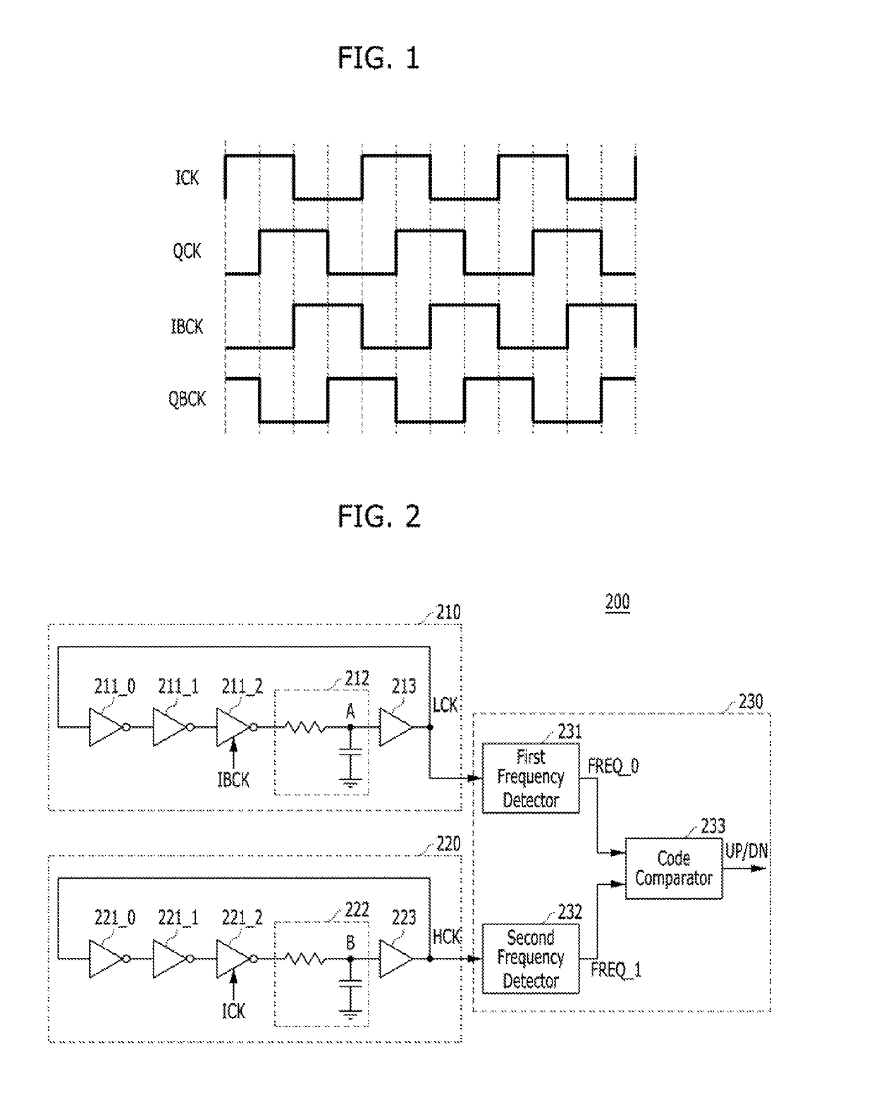
[0022]FIG. 2 is a block diagram illustrating a duty cycle detector 200 in accordance with an embodiment of the present disclosure. Referring to FIG. 2, the duty cycle detector 200 may include a first ring oscillator 210, a second ring oscillator 220, and a frequency comparator 230.

[0023]The first ring oscillator 210 may generate a first periodic wave (or a first periodic signal) LCK h...


PUM


Abstract

A duty cycle detector includes a first ring oscillator suitable for including an odd number of first inverters and generating a first periodic signal by using the first inverters, at least one inverter among the first inverters being enabled during a time interval when a clock has a first value, a second ring oscillator including an odd number of second inverters and suitable for generating a second periodic signal using the second inverters, at least one inverter among the second inverters being enabled during a time interval when the clock has a second value. The duty cycle detector further includes a frequency comparator suitable for comparing a frequency of the first periodic signal with a frequency of the second periodic signal and generating a duty cycle detection signal of the clock.

Description

CROSS-REFERENCE TO RELATED APPLICATION[0001]The present application claims priority to Korean Patent Application No. 10-2017-0140210, filed on Oct. 26, 2017, which is incorporated herein by reference in its entirety.BACKGROUND1. Field[0002]Illustrative embodiments of the present disclosure relate to a duty cycle detector for detecting a duty cycle of a clock, and a phase difference detector for detecting a phase difference between clocks.2. Description of the Related Art[0003]As the data transfer rates of diverse integrated circuits, such as a memory, are increased, using a clock of a high frequency to transfer data between integrated circuits becomes increasingly burdensome. In this respect, multi-phase clocks of lower frequencies than the frequency of the clock used for data transfer between integrated circuits may be used in an integrated circuit chip.[0004]FIG. 1 illustrates an example of multi-phase clocks. Referring to FIG. 1, four clocks ICK, QCK, IBCK, and QBCK may have a ph...

Claims


Application Information

Patent Timeline
Patent Type & Authority Applications(United States)
IPC IPC(8): H03K5/26H03K3/03H03K17/687H03H7/06G01R25/00
CPCH03K5/26H03K3/0315H03K17/687H03H7/06G01R25/00G01R29/023H03K5/1565
Inventor JEONG, DEOG-KYOONKIM, SUHWANCHAE, JOO-HYUNG
Owner SK HYNIX INC
Why Eureka
Try Eureka