Flavor inhaler

a technology of flavor inhaler and inhaler body, which is applied in the manufacture of cigars, tobacco smoke filters, tobacco, etc., to achieve the effect of improving the flavor favorable to users

Pending Publication Date: 2019-05-09
JAPAN TOBACCO INC
View PDF1 Cites 5 Cited by
  • Summary
  • Abstract
  • Description
  • Claims
  • Application Information

AI Technical Summary

Benefits of technology

[0005]In view of the above, the present invention has an object to provide a flavor inhaler that includes a combustible heat source carrying a flavorant in addition to a flavor source held in a main body and that is capable of expressing an enhanced flavor favorable to a user. More specifically, the present invention has an object to provide a flavor inhaler that hardly causes a chemical change of a flavorant during storage and does not express an undesirable flavor during use.
[0017]According to the present invention, a flavor inhaler capable of expressing an enhanced flavor favorable to a user can be provided.

Problems solved by technology

PCT National Publication No. 2010-535530, when a flavorant is carried on a combustible heat source to enhance the flavor, a problem occurs, such as a chemical change of the flavorant during storage or expression of an undesirable flavor due to heat during use, depending on a type of the flavorant.

Method used


Image

  • Flavor inhaler
  • Flavor inhaler
  • Flavor inhaler

Examples


example 1

Storage Test on First Flavorant

[0147][Process of Manufacturing Combustion Type Heat Source]

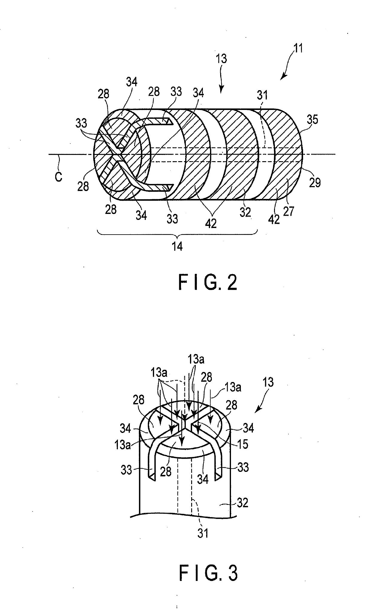
[0148]After mixing 235.5 g of highly activated carbon (BET specific surface area: 2050 m2 / g), 323.8 g of calcium carbonate, and 28.1 g of sodium carboxymethyl cellulose, 745.3 g of water containing 5.4 g of sodium chloride was added, and further mixed. After the mixture was kneaded, extrusion molding was carried out to have a cylindrical shape having an outer diameter of 6.5 mm. The molded product obtained by the extrusion molding was dried and then cut to a length of 13 mm to obtain a primary molded product.

[0149]A drill with a diameter of 1.0 mm was used to provide a through hole having an inner diameter of 1.0 mm at the center portion of the primary molded product. Cross groove processing was applied to one end surface of the primary molded product with a diamond cutting disc.

[0150]In this manner, the combustion type heat source 13 was manufactured in which the combustion type heat source 1...

example 2

Transfer Rate of First Flavorant to Mainstream Smoke

[0161][Manufacture of Combustion Type Heat Source]

[0162]The combustion type heat source 13 was manufactured according to the same method as that described in Example 1. As a result, the combustion type heat source 13 having the shape illustrated in FIG. 2 and containing the activated carbon having the BET specific surface area of 2050 m2 / g and having the activated carbon concentration of 39.7 wt % was manufactured.

[0163](Measurement Results of Transfer Rate to Mainstream Smoke)

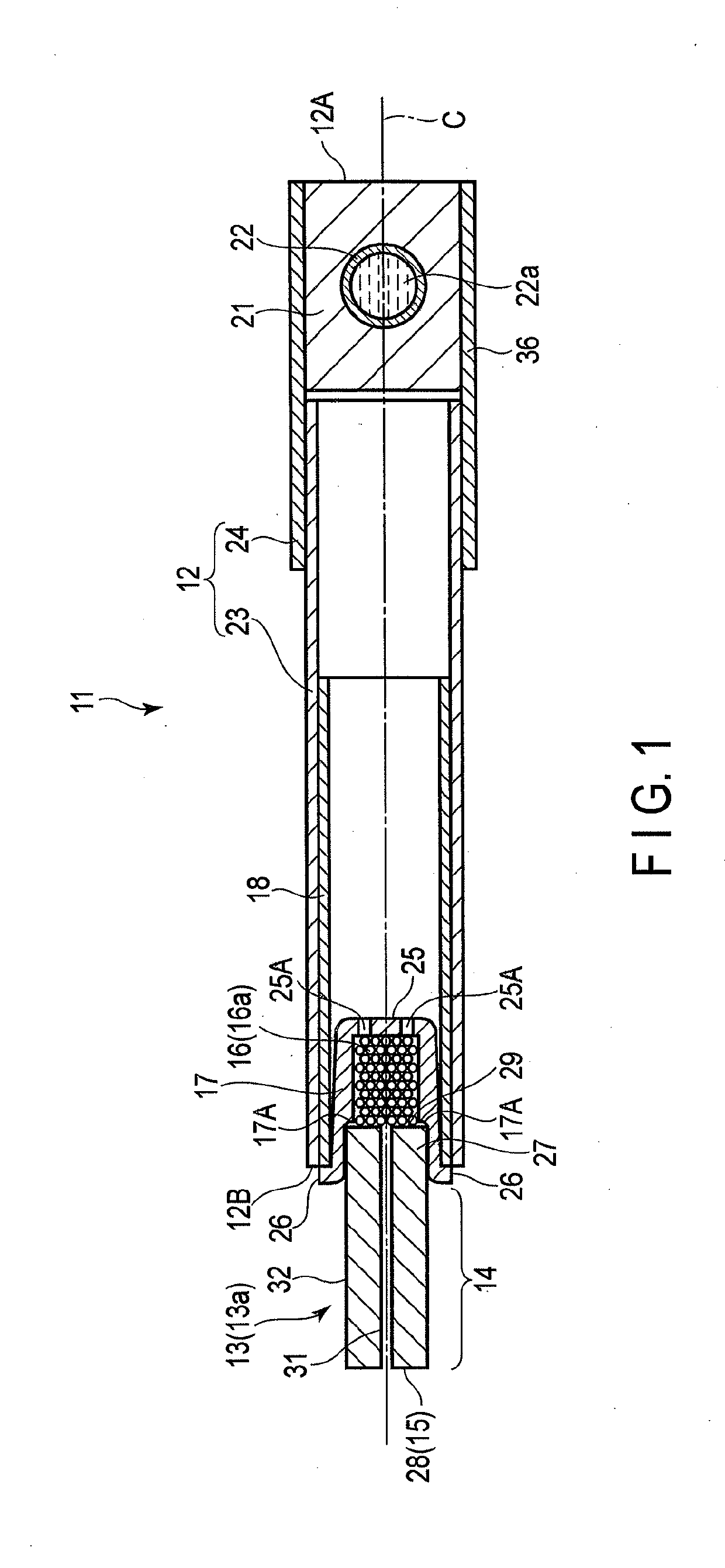
[0164]Anethole was carried on the combustion type heat source 13 according to the same method as that described in the Example 1. Using the combustion type heat source 13 carrying anethole, a flavor inhaler 11 shown in FIG. 1 was manufactured. Geraniol was used as the second flavorant, and menthol was used as the third flavorant.

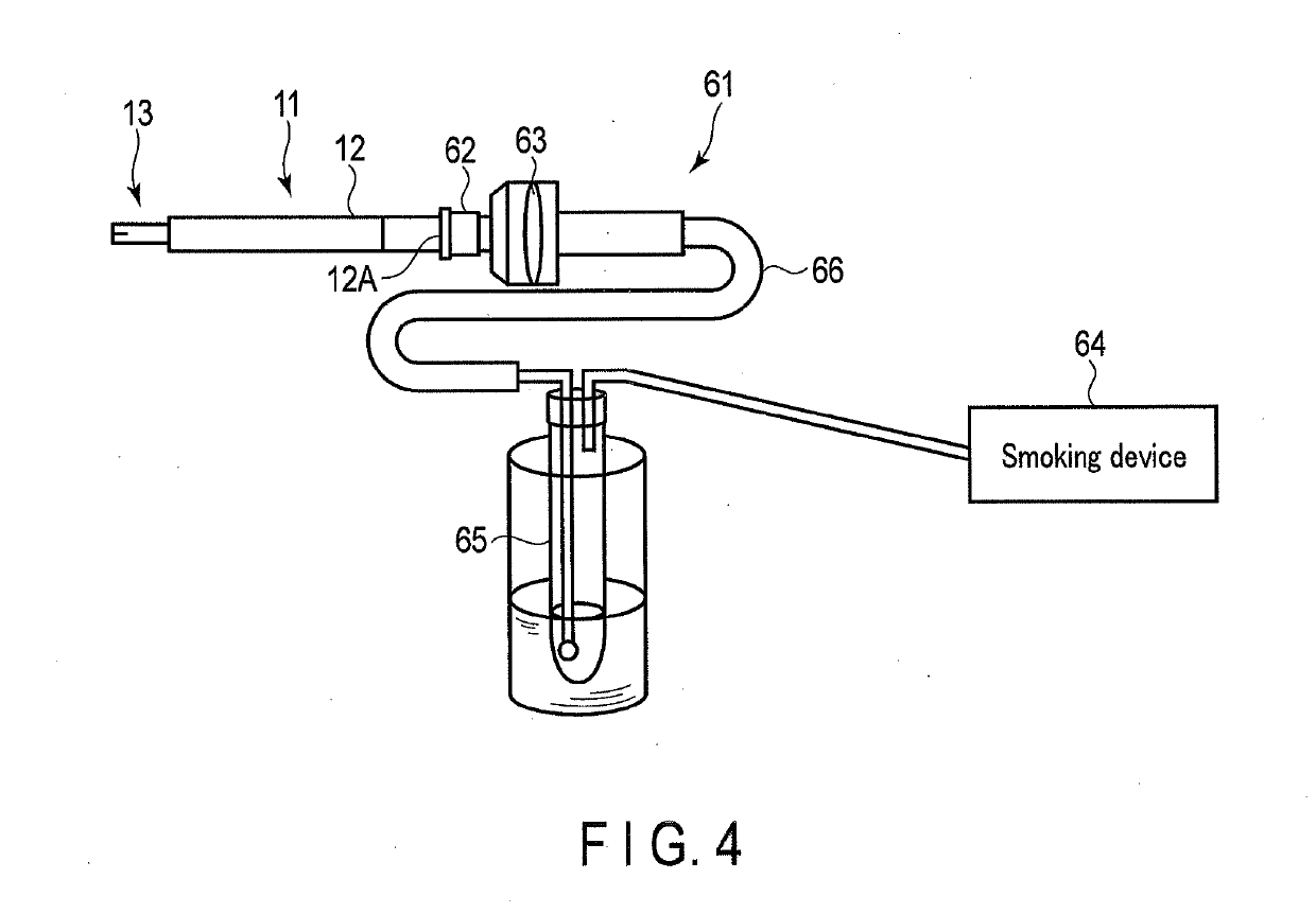
[0165]A measuring device 61 shown in FIG. 4 was used to measure the transfer rate of the flavorant (anethole) carried on the combust...

example 3

Example Using Menthol as First Flavorant

[0176]The combustion type heat source 13 was manufactured according to the same method as that described in Example 1. As a result, the combustion type heat source 13 having the shape illustrated in FIG. 2 and containing the activated carbon having the BET specific surface area of 2050 m2 / g and having the activated carbon concentration of 39.7 wt % was manufactured.

[0177]Menthol was carried on the combustion type heat source 13 according to the same manner as that described in Example 1. Using the combustion type heat source 13 carrying menthol, a flavor inhaler 11 (comparative example) shown in FIG. 1 was manufactured.

[0178]When the present inventors inhaled with the flavor inhaler 11 (comparative example), they sensed a metal-like undesirable flavor.


PUM


Abstract

A flavor inhaler comprising: a tubular holder that extends from a mouthpiece end to a distal end; a combustion type heat source that is provided at the distal end, contains activated carbon, and carries a first flavorant; and a flavor source that is held in the holder and carries a second flavorant, wherein the first flavorant contains at least one selected from the group consisting of anethole, 2-pinene, 3-citronellol, linalyl acetate, limonene, anisaldehyde, 4-terpineol, 2-β-pinene, jasmone, sabinene, linalool, 1,8-cineole, phenethyl alcohol, and myristicin, and the second flavorant contains at least one selected from the group consisting of α-terpinene, γ-terpinene, nerol, geraniol, and decanal.

Description

CROSS-REFERENCE TO RELATED APPLICATIONS[0001]This application is a Continuation Application of PCT Application No. PCT / JP2017 / 023782 filed Jun. 28, 2017 and based upon and claiming the benefit of priority from Japanese Patent Applications No. 2016-131585 filed Jul. 1, 2016, No. 2016-131586 filed Jul. 1, 2016, and No. 2016-131587 filed Jul. 1, 2016, the entire contents of which are incorporated herein by reference.BACKGROUND OF THE INVENTION1. Field of the Invention[0002]The present invention relates to a flavor inhaler capable of inhaling a flavor from a mouthpiece end.2. Description of the Related Art[0003]Jpn. PCT National Publication No. 2010-535530 discloses a distillation-based smoking article, that is, a smoking article including a combustible heat source, an aerosol generating substrate located downstream of the combustible heat source, and a heat conductive element located around a rear portion of the combustible heat source and a front portion of the aerosol generating subs...

Claims


Application Information

Patent Timeline
Patent Type & Authority Applications(United States)
IPC IPC(8): A24B15/16A24F47/00A24D3/06A24F7/04A24D1/22A24D3/17
CPCA24B15/165A24F47/006A24D3/061A24F7/04A24B15/167A24F42/10A24F42/60A24F42/80A24F42/00A24D3/06A24D1/22A24D3/17A24D1/002A24F40/40A24B15/16A24B15/18
Inventor NAKANO, TAKUMAAKIYAMA, TAKESHIODA, TAKASHISUZUKI, MASAAKINAKAZONO, TAKAYUKI
Owner JAPAN TOBACCO INC
Why Eureka
Try Eureka