Welding Equipment for Bridges

a technology for bridges and welding equipment, applied in the direction of bridges, soldering devices, auxillary welding devices, etc., can solve the problems of inconvenient adjustment of difficulty in adjusting welding so as to improve the performance of devices, improve the welding quality, and reduce the diameter of steel reinforcing cages

Active Publication Date: 2019-05-09
ZHENG SHANSHAN
View PDF0 Cites 27 Cited by
  • Summary
  • Abstract
  • Description
  • Claims
  • Application Information

AI Technical Summary

Benefits of technology

[0007]As an optimized technical proposal, the positioning recognizer is in electric connection with the impeller, so that automatic alignment of the steel bar steeve and the pulling sleeve can be realized to prevent the difference of diameters between the inner wall of two sides of steel reinforcing cage.
[0008]The benefits of the invention are as follows: when the equipment in the invention is in an initial state, the third guide sliding block is completely located in the third guide sliding groove, and the steel bar steeve is located at the position which is closest to the inner wall of the circular ring, and the welding ring stand abuts against the transverse block, and the pulling ring stand abuts against the welding ring stand and the inside welding plate is located in the welding cylindrical cavity, and the pulling sleeve and the steel bar steeve are located at the same horizontal line, so the convenience of the device is improved.
[0009]When the steel reinforcing cage for the bridge is welded by using the equipment of the invention, the longitudinal steel bars pass through the steel bar sleeve and pass through the welding cylindrical cavity and finally stretch into the pulling sleeve, and the transverse steel bars pass through the feed channel and are connected with the longitudinal steel bars; at the moment, the first motor, the second motor, the fourth motor and the fifth motor are started, and then the first motor drives the first adjusting threaded rod to rotate to make the welding ring stand move to one side, and the second motor drives the second adjusting threaded rod to rotate to enable the pulling ring stand to move to one side, and the fourth motor drives the second rotating gear to rotate to make the circular ring rotate, therefore continuous feed of steel bars of the steel reinforcing cage can be realized; meanwhile, external welding is carried out, and as the fifth motor drives the third adjusting threaded rod to rotate to make the inside welding plate move synchronously with the welding ring stand, so that the inner and outer simultaneous welding of the steel reinforcing cage can be realized, and the welding position also can be repeatedly welded and the welding quality can be improved.
[0010]When a steel reinforcing cage with different bore diameters needs to be welded, the third motor is started to drive the first rotating gear to rotate, and the third guide sliding block moves towards the center of the inner cavity of the circular ring under the action of the gear, so that the diameter of the steel reinforcing cage can be reduced; meanwhile, due to the positioning recognizer, the impeller is controlled by the positioning recognizer to enable the pulling sleeve to move towards the interior of the rotating disc until the pulling sleeve corresponds to the steel bar sleeve, so the performance of the device is improved.
[0011]The present invention is simple in structure and convenient to operate. The automatic shaping, wall-clamping type welding and automatic aligning and pulling mechanism are adopted, and all the mechanisms are separated from each other but couples with each other closely and not a single one can be omitted. The automation degree, welding quality and protection performance are quite high; meanwhile, the automatic diameter varying device is also arranged, and different series of steel reinforcing cages can be used for welding, so the practical performance is relatively high.

Problems solved by technology

In the technical field of the bridge welding, there has always been a difficult technical problem that a steel reinforcing cage needs to be welded in the general and normal bridge welding constructions, and the welding of the steel reinforcing cage requires the circumferential outer surface and the interior to be welded at the same time, but the ordinary welding machines only weld outside steel reinforcing cages, and the internal welding opening can not be welded.
Moreover, it is not easy to adjust the welding diameter of the steel reinforcing cage and not convenient to weld steel reinforcing cages with various diameters, however this device effectively solves the problem.

Method used


Image

  • Welding Equipment for Bridges
  • Welding Equipment for Bridges

Examples


Embodiment Construction

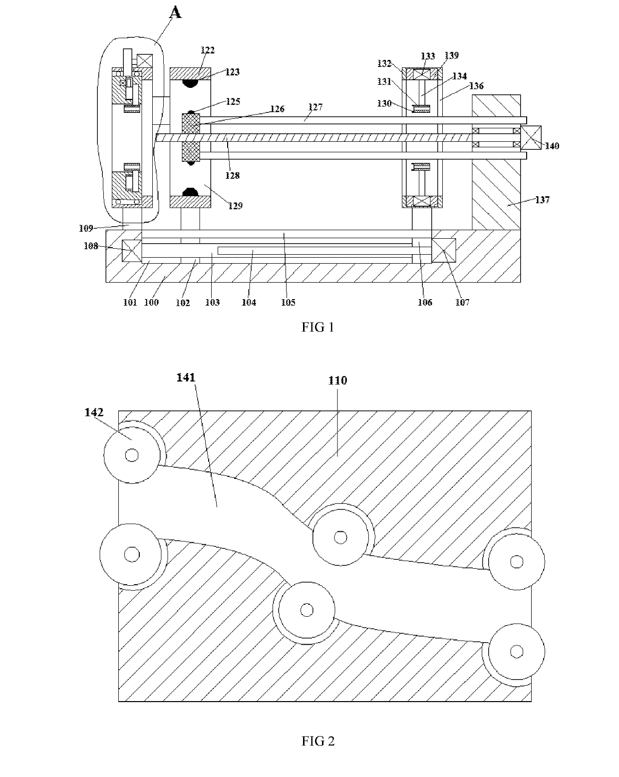
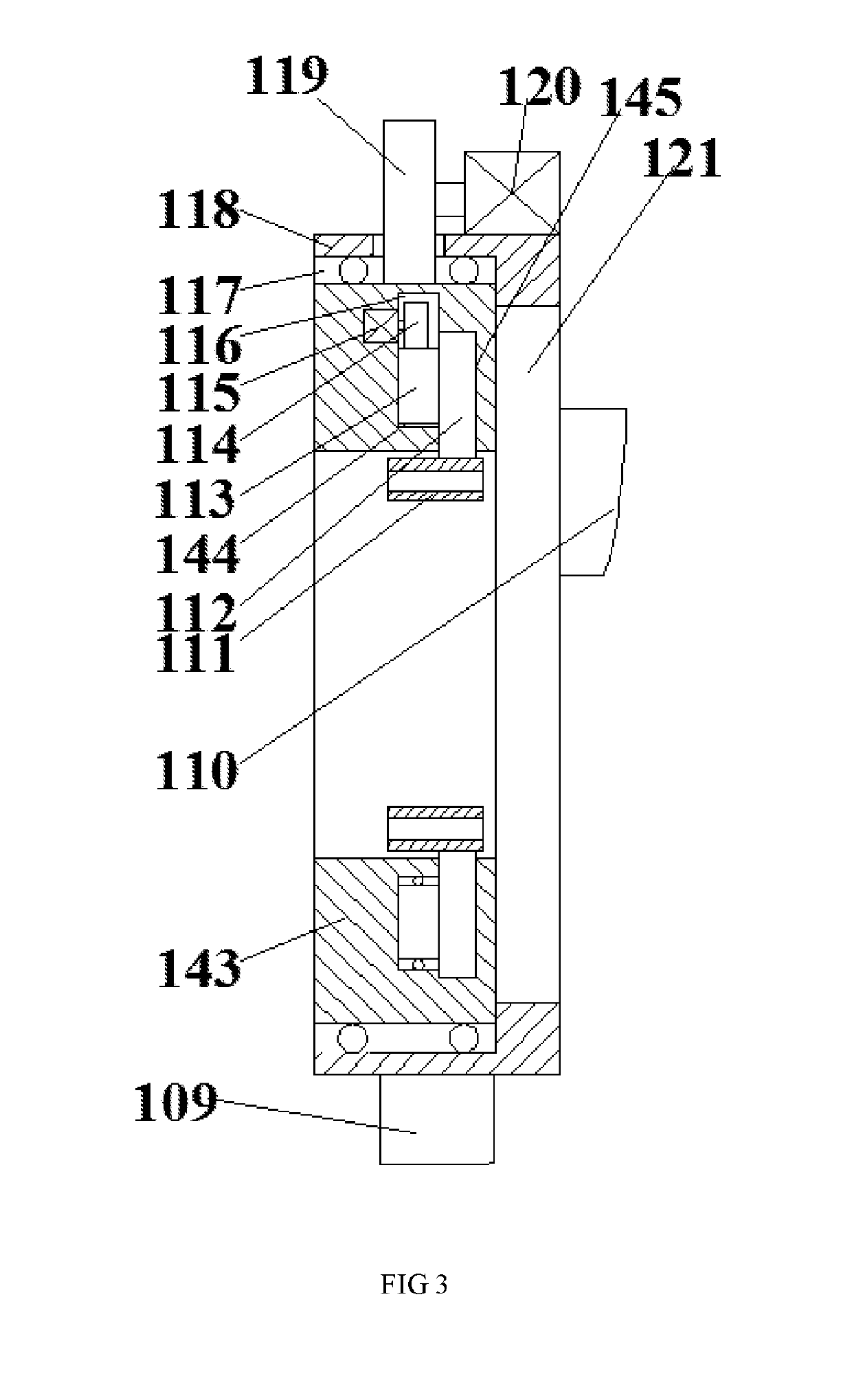
[0016]Referring to FIG. 1 to FIG. 3, a welding equipment for bridges in this invention comprises a base 100, a fixed ring stand 118 arranged on the top end surface of said base 100, a fixed block 109 fixedly connected with the top end surface of said base 100 arranged on the bottom end surface of said fixed ring stand 118, wherein a first guide sliding groove 101 with an upward opening and on one end of said fixed block 109 is arranged in the top end surface of said base 100, a first guide sliding block 102 in sliding fit connection with said first guide sliding groove 101, a welding ring stand 122 on one end of said fixed ring stand 118 fixedly connected to the top end surface of said first guide sliding block 102, wherein a first adjusting threaded rod 103 extending towards two ends is in threaded fit connection with the first guide sliding block 102, a first motor 108 in power connection with one tail end of said first adjusting threaded rod 103, wherein the outer surface of the ...


PUM

PropertyMeasurementUnit
speedaaaaaaaaaa
diametersaaaaaaaaaa
diameteraaaaaaaaaa

Abstract

This invention discloses a welding equipment for bridges, comprising a base, a fixed ring stand arranged on the top end surface of the base, a fixed block fixedly arranged on the bottom end surface of the fixed ring stand, wherein a first guide sliding groove is arranged in the top end surface of the base, a first guide sliding block in sliding fit connection with said first guide sliding groove. A welding ring stand is fixedly connected to the top end surface of said first guide sliding block; wherein a first adjusting threaded rod is in threaded fit connection with the first guide sliding block. A first motor is in power connection with one tail end of the first adjusting threaded rod. The first motor drives the first adjusting threaded rod to rotate to make the welding ring stand move to one side.

Description

CROSS-REFERENCES TO RELATED APPLICATIONS[0001]The present application claims priority from Chinese application No. 2018104673687 filed on May 16, 2018 which is hereby incorporated by reference in its entirety.TECHNICAL FIELD[0002]The invention relates to the technical field of bridge welding, in particular to a welding equipment for bridges.BACKGROUND OF THE INVENTION[0003]With the development of science and technology and the progress of society, the country has been promoting the development of high technology. In the technical field of the bridge welding, there has always been a difficult technical problem that a steel reinforcing cage needs to be welded in the general and normal bridge welding constructions, and the welding of the steel reinforcing cage requires the circumferential outer surface and the interior to be welded at the same time, but the ordinary welding machines only weld outside steel reinforcing cages, and the internal welding opening can not be welded. Moreover,...

Claims


Application Information

Patent Timeline
Patent Type & Authority Applications(United States)
IPC IPC(8): B23K20/00B23K20/02
CPCB23K20/002B23K20/02B23K37/0252B23K37/04B23K37/0276B23K37/0443B23K37/0452B23K37/047B23K31/02B23K2101/04B23K2101/22B23K2101/24E01D21/00
Inventor SHOU, JINXIAO
Owner ZHENG SHANSHAN
Why Eureka
Try Eureka