
System on chip

Active Publication Date: 2019-05-09
NUVOTON
View PDF1 Cites 3 Cited by
  • Summary
  • Abstract
  • Description
  • Claims
  • Application Information

AI Technical Summary

Benefits of technology

The disclosure describes a system-on-chip (SOC) that includes a system core logic, a voltage regulator, a clock generator, and a system balance circuit. The voltage regulator provides an operating voltage to the system core logic and can adjust its current mode based on a current setting signal. The clock generator provides a reference clock signal. The system balance circuit receives the reference clock signal and the current setting signal, and produces a system clock signal for the system core logic. This allows the voltage regulator to adjust its current mode before the system clock signal is enabled, and to switch to the low current mode after the system clock signal is enabled. The technical effect of this invention is to improve the performance and efficiency of the system circuit by optimizing the voltage regulation and clock synchronization.

Problems solved by technology

At this point, the voltage regulator itself has a bias far greater than the output load current and thus is not applicable to a low-power consumption system.

Method used


Image

  • System on chip
  • System on chip
  • System on chip

Examples


Embodiment Construction

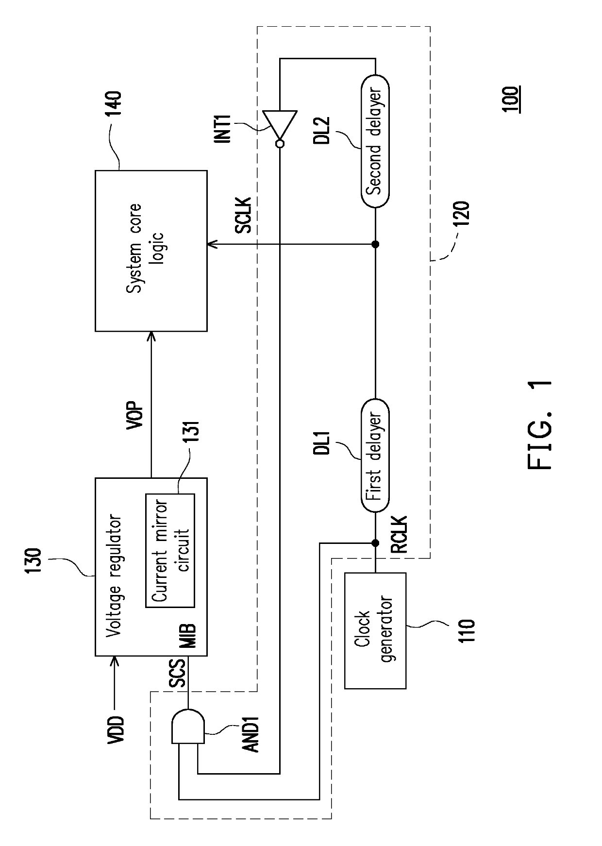
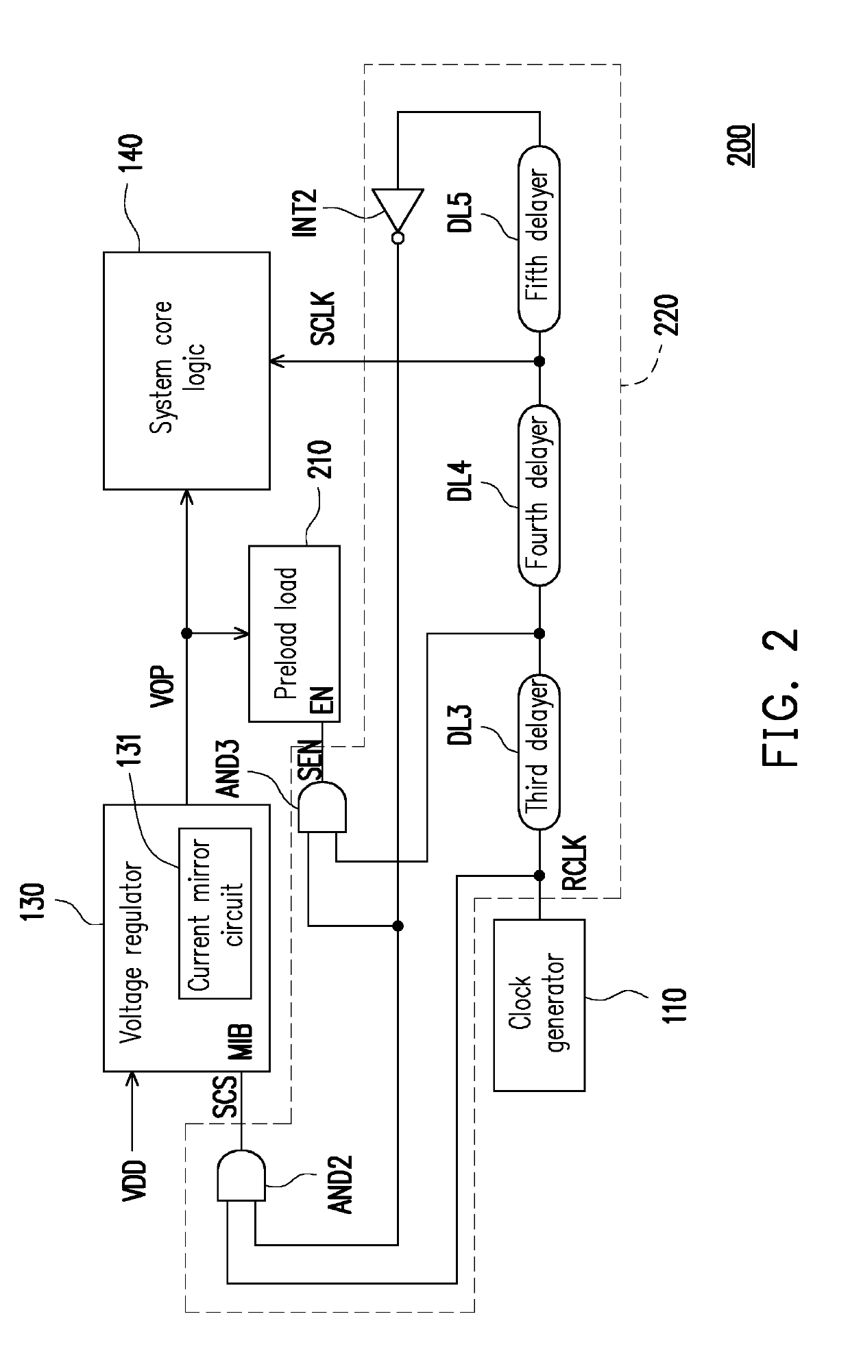
[0012]FIG. 1 is a schematic view showing a system of a SOC according to an embodiment of the disclosure. With reference to FIG. 1, in this embodiment, a SOC 100 includes a clock generator 110, a system balance circuit 120, a voltage regulator 130, and a system core logic 140. The clock generator 110 provides a reference clock signal RCLK, wherein a frequency of the reference clock signal RCLK is lower than 100 kHz. The voltage regulator 130 is coupled to the system core logic 140 and receives a power supply voltage VDD to provide an operating voltage VOP to the system core logic 140. A bias mode terminal MIB of the voltage regulator 130 receives a current setting signal SCS to set the voltage regulator 130 to a low current mode or a high current mode.

[0013]The system balance circuit 120 is coupled between the system core logic 140, the voltage regulator 130 and the clock generator 110 to receive the reference clock signal RCLK, provides the current setting signal SCS to the voltage ...


PUM


Abstract

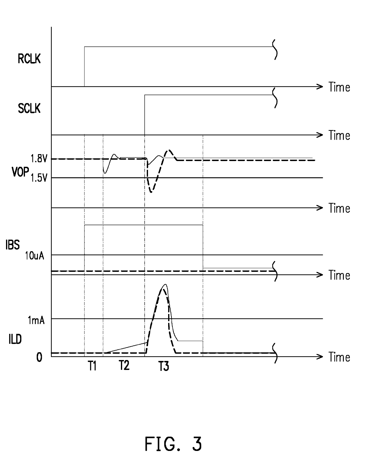
A system on chip (SOC) is provided. The SOC includes a system core logic, a voltage regulator, a clock generator and a system balance circuit. The voltage regulator provides an operating voltage to the system core logic and receives a current setting signal to set the voltage regulator to a low current mode or a high current mode. The clock generator provides a reference clock signal. The system balance circuit receives the reference clock signal to provide the current setting signal to the voltage regulator and provides the system clock signal to the system core logic, wherein the current setting signal is used to set the voltage regulator to the high current mode before the system clock signal is enabled, and set the voltage regulator to the low current mode after the system clock signal is enabled.

Description

CROSS-REFERENCE TO RELATED APPLICATION[0001]This application claims the priority benefit of Taiwan application no. 106138735, filed on Nov. 9, 2017. The entirety of the above-mentioned patent application is hereby incorporated by reference herein and made a part of this specification.BACKGROUNDTechnical Field[0002]The disclosure relates to a system on chip and particularly relates to a system on chip with low power consumption.Description of Related Art[0003]A voltage regulator is usually used to reduce an external input voltage to a lower operating voltage so as to provide the power required for a core logic circuit to operate. In order to cope with dramatic variations in an output load current, a bias current of the voltage regulator is usually designed to be greater than what is required to cope with these dramatic variations. However, when the system enters a low power mode, the output load current drops to several microamperes (μA) or even hundreds of nanoamperes (nA). At this ...

Claims


Application Information

Patent Timeline
IPC IPC(8): G05F3/26H03K5/135
CPCG05F3/26H03K5/135H03K19/20H03K2005/00078
Inventor WANG, CHENG-CHIH
Owner NUVOTON
Learn More