
High temperature nuclear fuel system for thermal neutron reactors

Inactive Publication Date: 2019-05-09
WESTINGHOUSE ELECTRIC CORP
View PDF0 Cites 10 Cited by
  • Summary
  • Abstract
  • Description
  • Claims
  • Application Information

AI Technical Summary

Benefits of technology

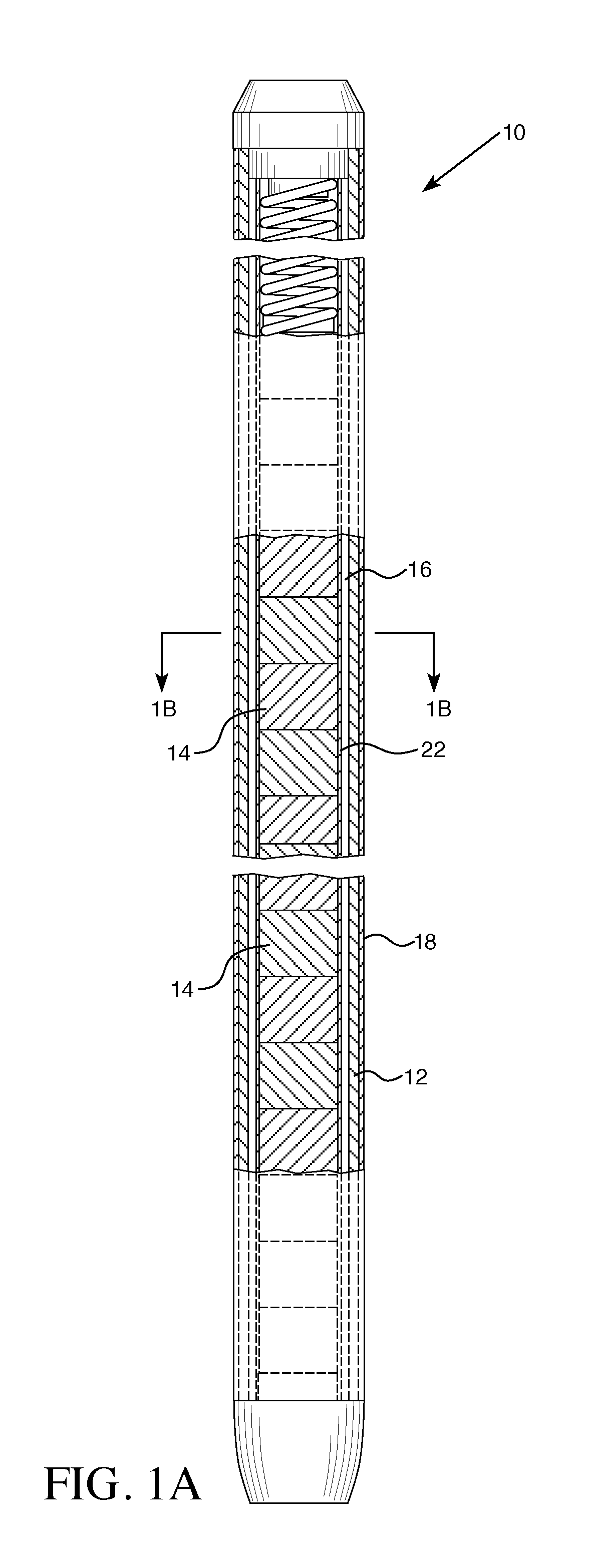
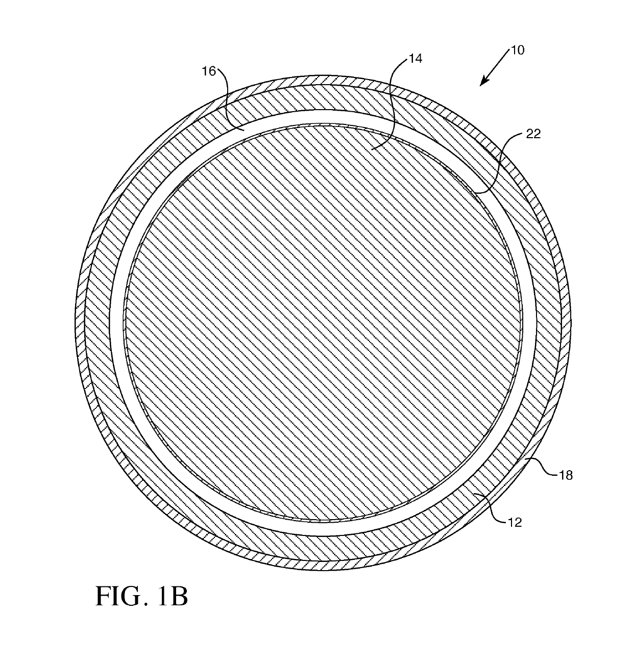
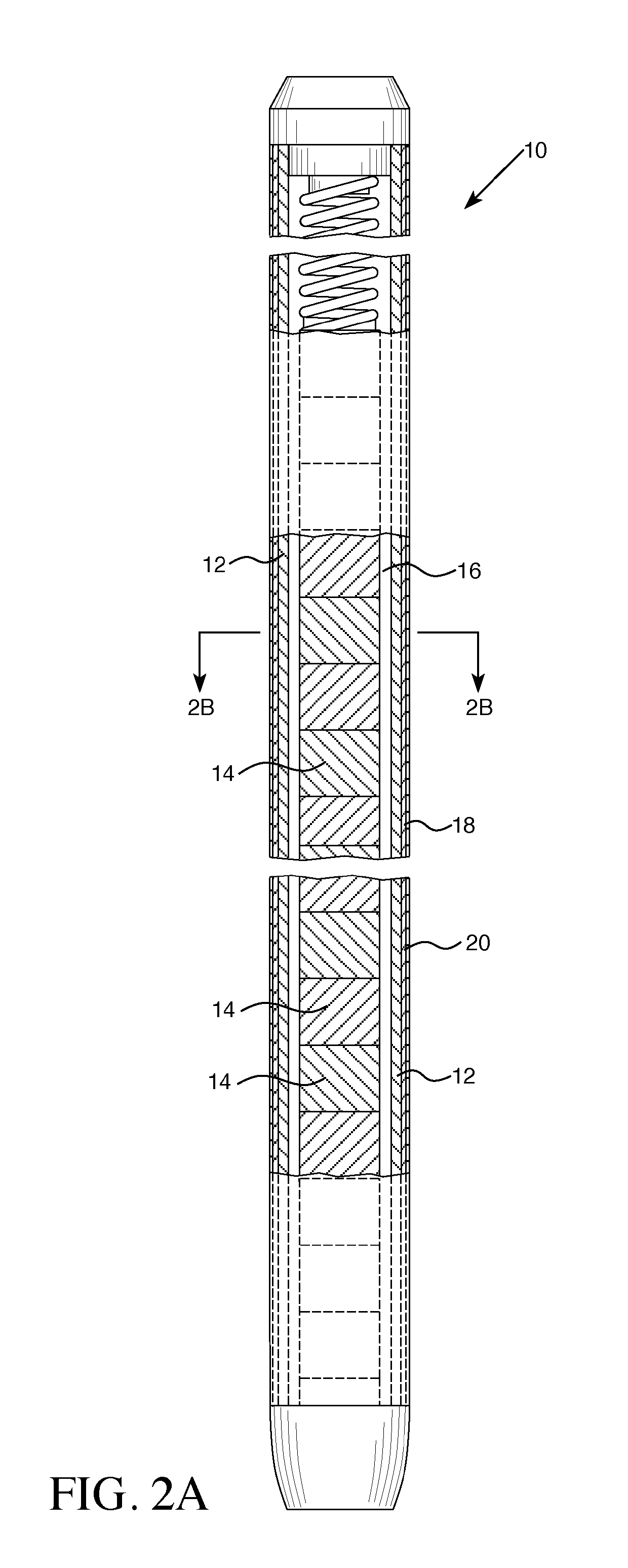
This patent describes an improved fuel rod design for use in reactors that can tolerate accidents. The fuel rod includes a nuclear fuel, a boron-containing absorber, and a cladding material. The cladding material may have a coating applied to it, which may be made of materials like Cr or Cr alloy. An interlayer may be included between the cladding material and the coating, which may be made of materials like Mo, Ta, W, or Nb. The burnable absorber may be intermixed with the nuclear fuel or coated on the exterior surface of the fuel pellet. Overall, this design improves the stability and safety of the fuel rod in the event of an accident.

Problems solved by technology

U3Si2 has a high density (12.2 gm / cm3), very high thermal conductivity (up to 5×UO2), and a melting point of 1665° C. To date, however, its use has been confined to lead test rods in test reactors where it is buried in a thick aluminum cladding which makes water coolant exposure unlikely, and where integral fuel burnable absorbers (IFBA) are not a required component of the fuel.
Suggestions for protecting and strengthening Zr claddings include coating the Zr alloy, but formation of a eutectic mixture can present a problem for coated Zr alloy claddings.
While a Zr alloy cladding coated, for example, with Cr initially provides up to 300° C. more temperature tolerance than does a Zr cladding alone, this increased tolerance comes at the expense of reduced cladding strength due to the formation of a liquid eutectic layer formed between the Cr coating and the Zr alloy cladding, thus lowering the melting temperature of the coated cladding, leaving the fuel susceptible to loss of coolant accidents.

Method used


Image

  • High temperature nuclear fuel system for thermal neutron reactors
  • High temperature nuclear fuel system for thermal neutron reactors
  • High temperature nuclear fuel system for thermal neutron reactors

Examples


Embodiment Construction

[0023]As used herein, the singular form of “a”, “an”, and “the” include the plural references unless the context clearly dictates otherwise. Thus, the articles “a” and “an” are used herein to refer to one or to more than one (i.e., to at least one) of the grammatical object of the article. By way of example, “an element” means one element or more than one element.

[0024]Directional phrases used herein, such as, for example and without limitation, top, bottom, left, right, lower, upper, front, back, and variations thereof, shall relate to the orientation of the elements shown in the accompanying drawing and are not limiting upon the claims unless otherwise expressly stated.

[0025]In the present application, including the claims, other than where otherwise indicated, all numbers expressing quantities, values or characteristics are to be understood as being modified in all instances by the term “about.” Thus, numbers may be read as if preceded by the word “about” even though the term “ab...


PUM


Abstract

An improved, accident tolerant fuel for use in light water and heavy water reactors is described. The fuel includes a zirconium alloy cladding having a chromium or chromium alloy coating and an optional interlayer of molybdenum, tantalum, tungsten, and niobium between the zirconium alloy cladding and the coating, and fuel pellets formed from U3Si2 or UN and from 100 to 10000 ppm of a boron-containing integral fuel burnable absorber, such as UB2 or ZrB2, either intermixed within the fuel pellet or coated over the surface of the fuel pellet.

Description

STATEMENT REGARDING GOVERNMENT RIGHTS[0001]This invention was made with government support under Contract No. DE-NE0008222 awarded by the Department of Energy. The U.S. Government has certain rights in this invention.BACKGROUND OF THE INVENTION1. Field of the Invention[0002]The invention relates to nuclear fuel, and more specifically to an accident tolerant fuel for use in light and heavy water reactors.2. Description of the Prior Art[0003]Fissile material for use as nuclear fuel includes uranium dioxide (UO2), plutonium dioxide (PuO2), uranium nitride (UN) either with natural nitrogen or nitrogen enriched in the 15N isotope, and / or tri-uranium disilicide (U3Si2), typically in pellet form. Fuel rods are encased in a cladding that acts as a containment for the fissile material. The cladding is preferably in the form of an elongate structure, such as a tube, and the fuel rod includes a plurality of pellets stacked in the cladding tube. In a typical fuel rod, the top and bottom ends of...

Claims


Application Information

Patent Timeline
IPC IPC(8): G21C3/07G21C1/04G21C3/62G21C7/04G21C3/04
CPCG21C3/07G21C1/04G21C3/626G21C7/04G21C3/047G21C3/20G21C21/02G21C3/045Y02E30/30G21C3/60G21C9/033
Inventor LAHODA, EDWARD J.XU, PENGOELRICH, JR., ROBERT L.BOYLAN, FRANK A.SHAH, HEMANTRAY, SUMITFRANCESCHINI, FAUSTOROMERO, JAVIER E.WRIGHT, JONATHAN
Owner WESTINGHOUSE ELECTRIC CORP
Learn More