Unlock instant, AI-driven research and patent intelligence for your innovation.

Ultrasound signal processing device and ultrasound signal processing method

a signal processing device and ultrasound technology, applied in ultrasonic/sonic/infrasonic image/data processing, instruments, applications, etc., can solve the problems of increasing the amount of calculation, increasing the cost of ultrasound diagnostic devices, and insufficient improvement so as to suppress the decrease of spatial resolution and signal to noise ratio, the effect of reducing the calculation amoun

Active Publication Date: 2019-05-23
KONICA MINOLTA INC
View PDF0 Cites 0 Cited by
  • Summary
  • Abstract
  • Description
  • Claims
  • Application Information

AI Technical Summary

Benefits of technology

This patent is about a device that processes ultrasound signals. The device aims to reduce the calculation needed while maintaining the quality of the ultrasound signals. This device can be used in ultrasound diagnostic devices. The technical effect is to improve the efficiency and accuracy of ultrasound signals processing.

Problems solved by technology

However, when increasing spatial resolution to achieve high resolution, the number of observation points included increases in proportion to the resolution, and therefore regarding delay-and-sum processing in view of transmission and reception delay, an amount of calculation increases.
For this reason, hardware with high calculation processing capacity is required for high speed delay-and-sum calculation processing, which causes a problem of the cost of an ultrasound diagnostic device increasing.
On the other hand, if the number of observation points is simply reduced, spatial resolution and signal to noise ratio may be insufficiently improved.

Method used


Image

  • Ultrasound signal processing device and ultrasound signal processing method
  • Ultrasound signal processing device and ultrasound signal processing method
  • Ultrasound signal processing device and ultrasound signal processing method

Examples


embodiment 2

[0112]According to the ultrasound signal processing device 150 pertaining to Embodiment 1, the delay-and-sum section 1043, in correspondence with a transmission event, is configured to set a calculation target region Bx as a rectilinear region that passes through an array center of the reception aperture Rx, is perpendicular to the transducer array, and has a width of a single transducer. Further, the delay-and-sum section 1043 is configured to generate acoustic line signals by performing delay-and-sum with respect to reception signal sequences received by reception transducers from a plurality of observation points in the calculation target region Bx. However, the calculation target region Bx is not limited to this example, and may be set as any region included in the ultrasound primary irradiation region Ax. According to the ultrasound signal processing device pertaining to Embodiment 2, the calculation target range Bx is set to a range substantially equal to the ultrasound primar...

« modification 1

«Modification 1»

[0155]According to at least one embodiment, a probe configuration is illustrated in which the transducers 101a are arranged along a one-dimensional direction. However, configuration of the probe 101 is not limited to this. For example, a two-dimensional transducer array in which the transducers 101a are arrayed on a two-dimensional plane or a rocking-type probe that acquires a three-dimensional tomographic image by mechanical rocking of a plurality of transducers arranged along a one-dimensional direction may be used as appropriate, depending on measurement requirements.

[0156]FIG. 22 is a schematic plan view diagram illustrating an aspect of transducers 101Ba of a probe 101B used in an ultrasound signal processing device pertaining to Modification 1. In the probe 101B, the transducers 101Ba are arranged in two dimensions (X1, X2), and by individually changing timing of voltage application and voltage values applied to the transducers 101Ba, it is possible to control ...

« modification 2

«Modification 2»

[0162]According to the ultrasound diagnostic device 100 pertaining to at least one embodiment, the delay-and-sum section 1043, with respect to a reference observation point PRij selected from observation points in a region of interest corresponding to an analysis target range of a subject, calculates a delay time of arrival of a reflected wave from the reference observation point PRij to each reception transducer Rwk as a reference delay time Δtk and generates acoustic line signals DS by using the reference delay time Δtk for each reception transducer Rwk. Further, with respect to one or more dependent observation points PFij that are contiguous in the depth direction from the reference observation point PRij, the delay-and-sum section 1043 generates acoustic line signals DS by using the reference delay time Δtk with respect to each of the reception transducers Rwk.

[0163]However, according to an ultrasound signal processing device pertaining to Modification 2, the re...


PUM


Abstract

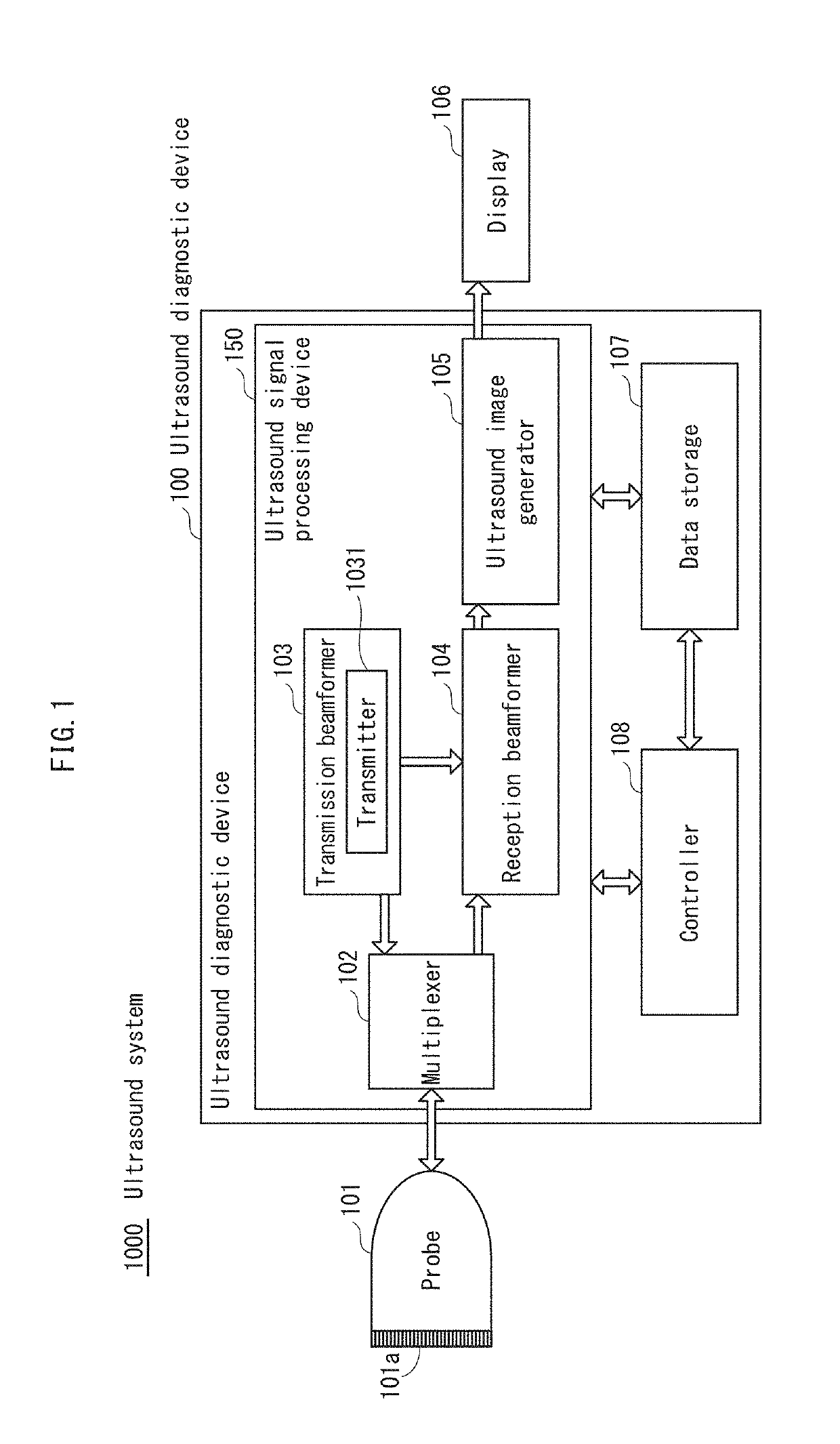
An ultrasound signal processing device including: a transmitter 103 that causes transducers 101a to transmit an ultrasound beam; a receiver 1041 that, based on reflected waves received by reception transducers Rwk, generates reception signal sequences RFk corresponding to the reception transducers Rwk; and a delay-and-sum section 1043 that, for a reference observation point PRij in a region of interest, calculates delay times of reflected wave arrival to each of the reception transducers Rwk from the reference observation point PRij as reference delay times Δtk, and generates acoustic line signals DS by using the reference delay times Δtk corresponding to the reception transducers Rwk, and for one or more dependent observation points PFij in the region of interest that are contiguous in a depth direction from the reference observation point PRij, generates acoustic line signals DS by applying the reference delay times Δtk corresponding to the reception transducers Rwk.

Description

[0001]This application claims priority to Japanese Patent Application No. 2017-223158, filed Nov. 20, 2017, the contents of which are hereby incorporated by reference in their entirety.BACKGROUND OF THE DISCLOSURETechnical Field[0002]The present disclosure relates to ultrasound signal processing devices and ultrasound signal processing methods, and in particular to reception beamforming processing methods in ultrasound diagnostic devices.Description of the Related Art[0003]An ultrasound diagnostic device transmits ultrasound to an inside of a subject via an ultrasound probe (hereinafter also referred to as a probe) and receives ultrasound reflected waves (echoes) caused by a difference in acoustic impedance of tissue in the subject. Further, based on an electric signal obtained from reception, an ultrasound diagnostic image illustrating structure of internal tissue of the subject is generated and displayed on a monitor (hereinafter also referred to as a display). Ultrasound diagnost...

Claims


Application Information

Patent Timeline
Patent Type & Authority Applications(United States)
IPC IPC(8): A61B8/00G01S7/52A61B8/08A61B8/13
CPCA61B8/4272G01S7/52028A61B8/0858A61B8/13G01S7/52046G01S15/8927G01S7/52085A61B8/5207G10K11/346
Inventor WATANABE, YASUHITO
Owner KONICA MINOLTA INC