Recirculating gradient power system

a gradient power system and gradient technology, applied in the direction of fluid-pressure actuators, machines/engines, motors, etc., can solve the problems of unsatisfactory unsatisfactory ideal position in which the carrier obtains the optimum gravity energy, and interruption of the operation of the gravity oscillating system, etc., to achieve the effect of increasing the conversion of kinetic energy and increasing the gravity potential energy

Inactive Publication Date: 2019-05-23
IMUSHROOM DIGITAL LTD
View PDF20 Cites 0 Cited by
  • Summary
  • Abstract
  • Description
  • Claims
  • Application Information

AI Technical Summary

Benefits of technology

[0019]More specifically, the circulating gradient power system of the prevent invention has a track annularly disposed on the motion carrier, the surface of the track has the wear-resistant structure, and thus when the track has been worn or damaged, merely the track should be replaced without replacing the whole motion carrier. Further, the counterweight is disposed at a position where the center of mass of the counterweight is located at an outer side of the motion carrier, the counterweight can have the larger gravity potential energy, and thus, the converted kinetic energy becomes larger.

Problems solved by technology

However, the heavy ball may be easily intercepted by an unexpected external force during the rolling process, causing the operation of the gravity oscillating system to be interrupted.
In addition to the problem of replacing the whole platform (or other similar components) as mentioned above, since the mass center of the carrier is located on the platform, when the platform is tilted by the gravity applying on the carrier, the highest position which the carrier (or other similar components) as mentioned above is positioned is not the ideal position which the carrier obtains the optimum gravity energy.
This also causes the converted kinetic energy is not ideal, after the subsequent carrier rotates from the high point to the low point to convert the gravity potential energy into kinetic energy.

Method used


Image

  • Recirculating gradient power system
  • Recirculating gradient power system
  • Recirculating gradient power system

Examples


Embodiment Construction

[0035]Embodiments of the present invention will now be described, by way of example only, with reference to the accompanying drawings.

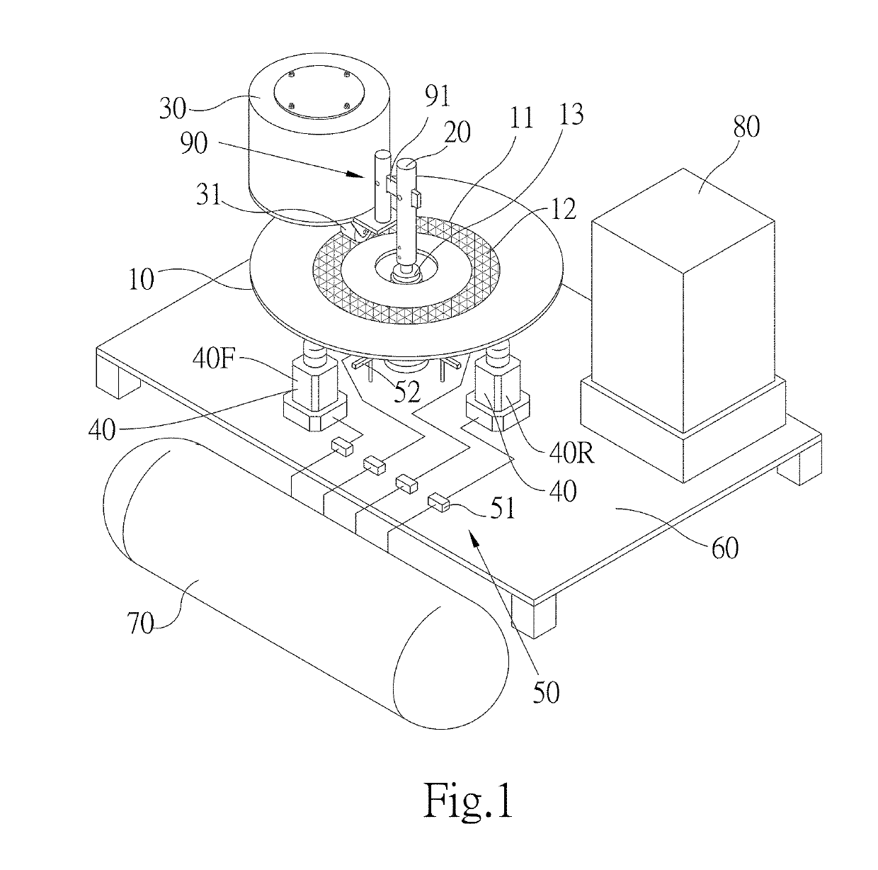
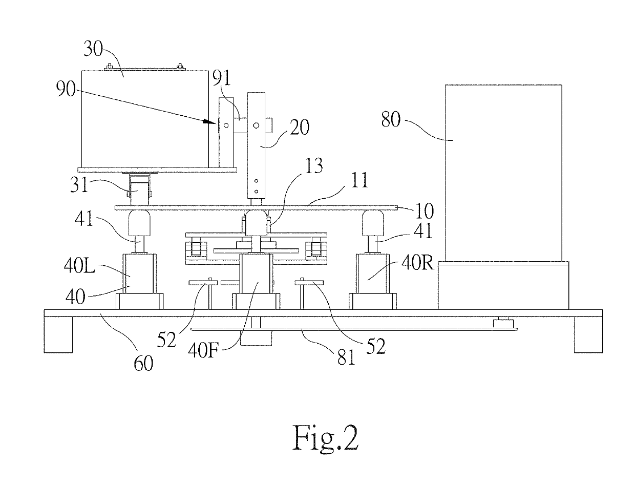
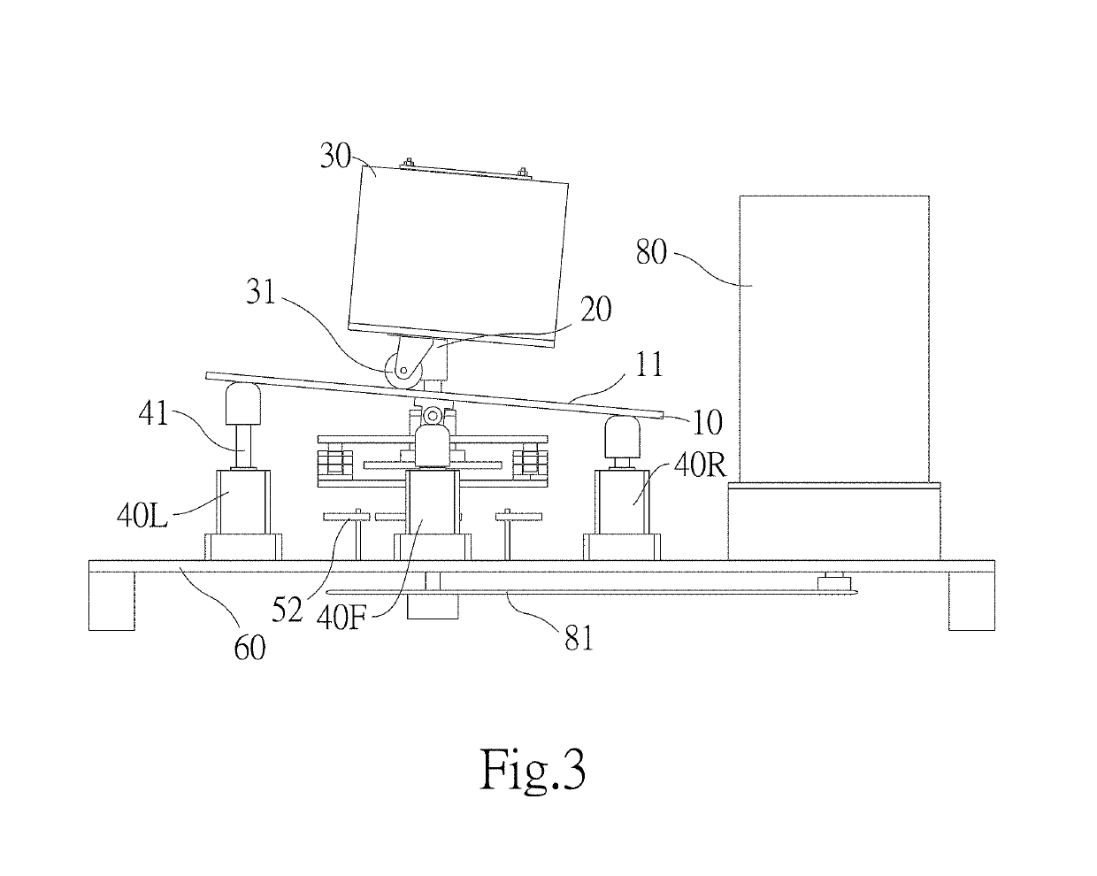
[0036]The present invention mainly provides a recirculating gradient power system. As shown in FIG. 1 and FIG. 2, the recirculating gradient power system of the present invention substantially comprises a motion carrier 10, a rotating shaft 20, a counterweight 30, a plurality of power cylinders 40, and a control module 50.

[0037]The motion carrier 10 is horizontally arranged and has a central vertical axis as a pivot to change its tilt orientation and tilt angle. In an embodiment, the motion carrier 10 may be a mechanical structure formed of a metal, a wood, plastics or a foam material by processing.

[0038]The rotating shaft 20 is vertically disposed at the position of the central vertical axis of the motion carrier 10.

[0039]The counterweight 30 is pivotally connected to the rotating shaft 20 through a coupling mechanism 90, and is rotationally displace...


PUM


Abstract

A recirculating gradient power system includes a motion carrier, a counterweight, power cylinders and a control module. A central vertical axis of the motion carrier has a rotating shaft pivotally connected with the counterweight. The power cylinders connected with a pressure source are evenly arranged at diagonal corners around the periphery of the central vertical axis. The control module connected with the power cylinders controls operation of the power cylinders which are set in advance when the counterweight is rotationally displaced to a predetermined stroke. The pressure source sequentially provides compressed gas fluid to the power cylinders to make the motion carrier continuously change its tilt orientation and tilt angle, thus forming a virtual continuous gradient. The counterweight is rotationally displaced from a high point of the motion carrier toward a lower point of the motion carrier about the rotating shaft by gravity, and the rotating shaft rotates continuously.

Description

CROSS-REFERENCE TO RELATED APPLICATION[0001]This application is a continuation-in-part of U.S. patent application Ser. No. 15 / 499,992, filed at Apr. 28, 2017, claiming priority to China patent application No. 201610317269.1 filed at May 13, 2016.FIELD OF THE INVENTION[0002]The present invention relates to a power output system, and more particularly to a recirculating gradient power system, wherein a motion carrier changes its tilt orientation and tilt angle to make a counterweight is rotationally displaced from a high point of the motion carrier toward a lower point of the motion carrier about a rotating shaft, thus forming the rotating motion of the rotating shaft.BACKGROUND OF THE INVENTION[0003]GB Patent GB2527102A provides a gravity oscillating system for generating electrical power. GB2527102A discloses that a plurality of electromagnets are momentarily energized to move the track down ahead of the rolling mass (a heavy ball), when the electromagnets is energized, the electron...

Claims


Application Information

Patent Timeline
Patent Type & Authority Applications(United States)
IPC IPC(8): F03G3/00F03G7/08F15B15/06F15B15/14
CPCF03G3/00F03G7/08F15B15/06F15B15/1409F05B2260/403F03G7/104
Inventor LO, CHI-CHUNGLEE, MING-HSIU
Owner IMUSHROOM DIGITAL LTD
Why Eureka
Try Eureka