Device with hatch for additive manufacturing

Active Publication Date: 2019-05-30
SIEMENS ENERGY GLOBAL GMBH & CO KG
View PDF0 Cites 0 Cited by
  • Summary
  • Abstract
  • Description
  • Claims
  • Application Information

AI Technical Summary

Benefits of technology

The present invention provides a device that simplifies the manufacture of components with a large aspect ratio and makes it possible to achieve a continuous and uninterrupted buildup of components using powder-bed-based additive manufacturing. The device also facilitates the separation of subportions of the component for a continuous buildup in layers, without the need for interruption of the buildup process. Additionally, the device allows for a continuous feed of new starting material for the component and ensures a flowing and continuous buildup. These technical effects improve the efficiency and speed of additive manufacturing and make it suitable for the production of components with complex designs.

Problems solved by technology

At the current time, the designs of the components are limited, in particular in terms of their dimensions, by the design of the commercially available systems which in particular offer only a limited building space.
Consequently, a very large amount of powder has to be used for the manufacture of the corresponding component and in particular arranged or moved in the building space.
This constitutes a substantial disadvantage for the technology of additive manufacturing since the powder is not only expensive but any unnecessary (further) use of the powder can be disadvantageous for the component and also for the method.
In particular, powder for each additive manufacturing process that is not processed to form the component is thermally loaded by the manufacturing conditions, for example by a laser, which can lead to an ageing process and thus to an impairment of the physical properties of the powder.
Furthermore, a large quantity of powder has to be kept in stock, for example, with it being the case that, during each (renewed) heating of the powder in the building space, the quality of the powder can be impaired by a partial oxidation and / or by the absorption of air moisture.

Method used


Image

  • Device with hatch for additive manufacturing

Examples


Embodiment Construction

[0039]Furthermore, on the basis of the figures, a method according to the invention for additive manufacturing and a component which is produced or can be produced correspondingly are described.

[0040]In the exemplary embodiments and figures, identical or identically acting elements can each be provided with the same reference signs. The illustrated elements and their mutual size ratios are fundamentally not to be considered as true to scale; rather, for better illustrability and / or for better understanding, individual elements may be illustrated as exaggeratedly thick or greatly dimensioned.

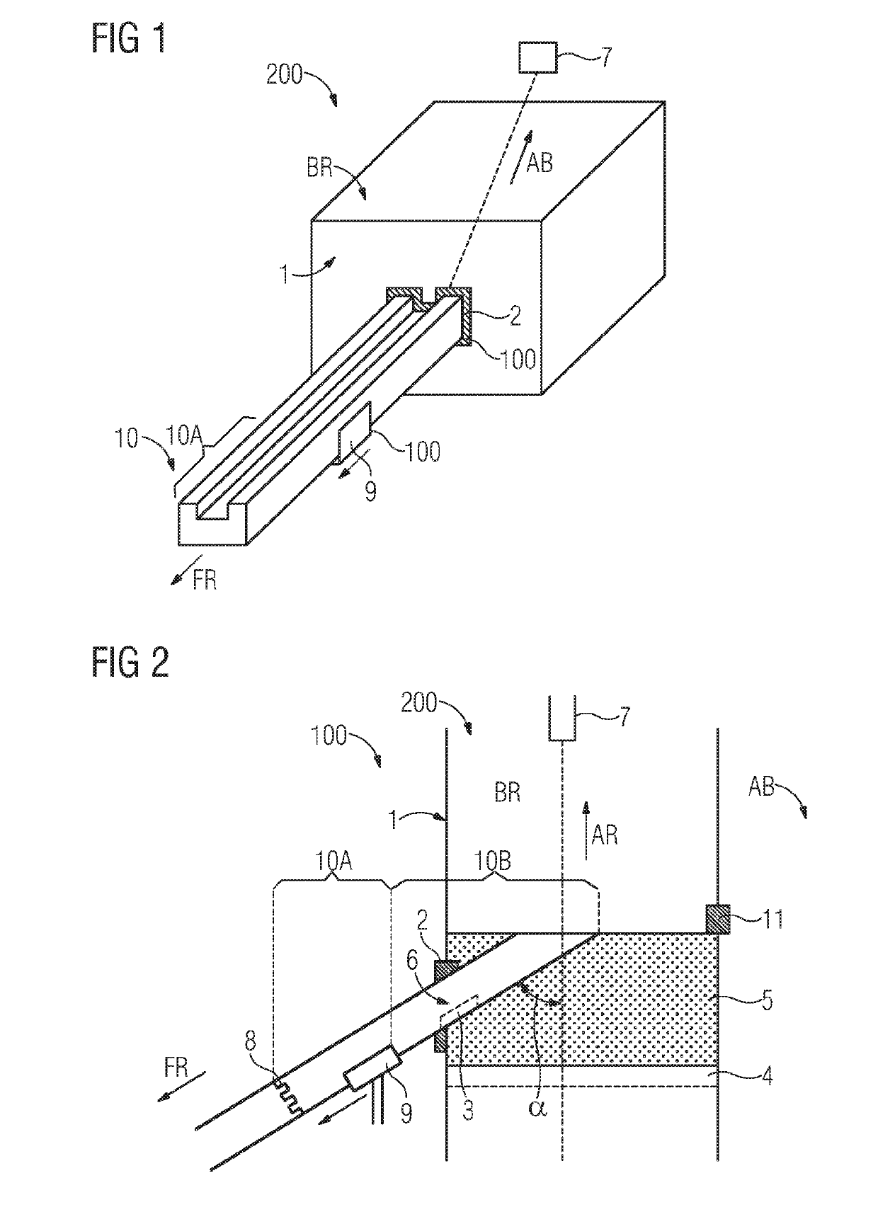
[0041]FIG. 1 shows a system 200. The system 200 is advantageously a system, in particular for the powder-bed-based, additive manufacturing of a component 10.

[0042]In the present case, the term “component” can be used to designate a component which at least partially is still to be built up and a ready-produced component.

[0043]The system 200 is advantageously a system for the additive manufacturin...


PUM

PropertyMeasurementUnit
Angleaaaaaaaaaa
Angleaaaaaaaaaa
Structureaaaaaaaaaa

Abstract

A device for additive manufacturing, in particular powder-bed-based additive manufacturing, having a build-chamber wall, which defines a build chamber and is designed to separate the build chamber from an outside area. The build-chamber wall has a hatch, which is designed for transferring at least partially a component that is to be built up in layers from the build chamber through the hatch into an outside area during an additive manufacturing process, and the component can be built up along at least one transferring direction beyond a dimension of the build chamber. A corresponding method includes the provision of a first portion of the component to be manufactured in layers in the build chamber, and the building up in layers of a second portion, adjoining the first portion, wherein an already built-up sub-portion of the component is transferred in layers from the build chamber through the hatch into the outside area.

Description

CROSS REFERENCE TO RELATED APPLICATIONS[0001]This application is the US National Stage of International Application No. PCT / EP2017 / 059142 filed Apr. 18, 2017, and claims the benefit thereof. The International Application claims the benefit of German Application No. DE 102016207896.8 filed May 9, 2016. All of the applications are incorporated by reference herein in their entirety.FIELD OF INVENTION[0002]The present invention relates to a device for the, in particular powder-bed-based, additive manufacturing of a component and to a system comprising the device. Also described are a corresponding method for the additive manufacturing of the component and a component which is produced or can be produced correspondingly.[0003]The component can be provided for use in a turbomachine, in particular a gas turbine. In particular, the present invention further relates to components having a particularly large aspect ratio or components which are to be built up additively over a large length.BA...

Claims


Application Information

Patent Timeline
IPC IPC(8): B29C64/379B29C64/25B29C64/153
CPCB29C64/379B29C64/25B29C64/153B29C64/268B22F3/1055B33Y10/00B33Y30/00B33Y40/00B33Y80/00B29C64/20B29C64/371Y02P10/25B22F12/30B22F10/28B22F12/38B22F10/32
Inventor OTT, MICHAEL
Owner SIEMENS ENERGY GLOBAL GMBH & CO KG
Why Eureka
Try Eureka