Process for the production of solvent stable polymeric membranes

a polymer membrane and solvent stable technology, applied in membrane technology, membrane filtration, reverse osmosis, etc., can solve the problems of increasing the brittleness of the membrane, difficult manufacture and use, and not widely applied to the separation of solutes in organic solvents, and achieves the effect of higher permean

Active Publication Date: 2019-06-13
IP2IPO INNOVATIONS LTD
View PDF7 Cites 7 Cited by
  • Summary
  • Abstract
  • Description
  • Claims
  • Application Information

AI Technical Summary

Benefits of technology

[0017]Further, the membranes of the present invention can be employed in a feed stream solution in which the solution is strongly acidic or basic, or in which the feed stream solution contains components which are strongly acidic or basic. This is advantageous with respect to the prior art membranes, which lose structure and dissolve under strongly acidic or basic conditions. The membranes of the present invention however are stable in these solvents, offering acceptable permeance and rejections.
[0018]Yet a further advantage of the membranes of the present invention is that they may exhibit higher permeance than known membranes when mixtures of water and organic solvent are being processed.
[0019]Yet a further advantage of the membranes of the present invention is that residual functional groups from the cross-linking agent are passivated by reaction with the cross-link modification agent.
[0020]Yet a further advantage of the membranes of the present invention is that they demonstrate consistent performance over time.
[0021]Yet a further advantage of the membranes of the present invention is that the cross-link modification agent may be chosen to alter the properties of the membrane so as to modulate permeance and / or rejection of the membrane.

Problems solved by technology

Ultrafiltration and nanofiltration have been widely applied to the filtration of aqueous fluids, but due to a lack of suitable solvent stable membranes they have not been widely applied to the separation of solutes in organic solvents.
However, these methods are known to lead to a dramatic increase in the brittleness of the membranes, making them difficult to manufacture and use.

Method used


Image

  • Process for the production of solvent stable polymeric membranes
  • Process for the production of solvent stable polymeric membranes
  • Process for the production of solvent stable polymeric membranes

Examples


example 1

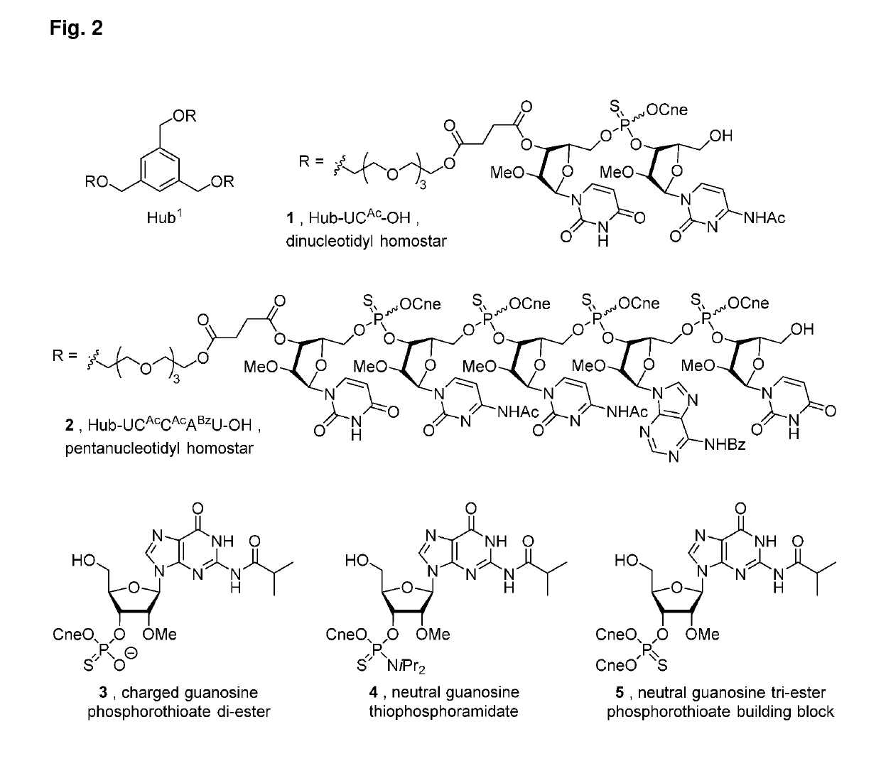
[0233]The membrane performance was determined by filtration experiments. A laboratory scale cross-flow nanofiltration unit was used with 4 cross-flow cells in series. Membrane discs of active area 14 cm2 were used. An 80 mL feed tank was charged with a feed solution consisting of 0.04 g of tris(dinucleotidyl)hub1 homostar 1 (see FIG. 2). The feed solution was re-circulated at a flow rate of 60-180 L h−1 using a Micropump (GD series, Michael Smith Engineers Ltd., UK). Pressure in the cells was generated using a backpressure regulator which was located down-stream of a pressure gauge. During start-up, the non-reactive conditioning solution was removed by re-circulating pure solvent and discarding the initial permeate. During operation, permeate samples were collected from individual sampling ports for each cross-flow cell and the retentate sample was taken from the recycle line. The solvent flux Nv was calculated from the equation (1):

Nv=VAt(1)

where V=volume of a liquid sample collect...

example 2

[0236]A laboratory scale cross-flow nanofiltration unit was used with 4 cross-flow cells in series. Membrane discs of active area 14 cm2 were used. An 80 mL feed tank was charged with a feed solution consisting of 0.04 g of tris(dinucleotidyl)hub1 homostar 1 or 0.06 g tris(pentanucleotidyl)hub1 homostar 2 with 0.02 g neutral tri-ester guanine nucleotide 5 (see FIG. 2). The feed solution was re-circulated at a flow rate of 60-180 L h−1 using a Micropump (GD series, Michael Smith Engineers Ltd., UK). Pressure in the cells was generated using a backpressure regulator which was located down-stream of a pressure gauge. During start-up, the non-reactive conditioning solution was removed by re-circulating pure solvent and discarding the initial permeate. During operation, permeate samples were collected from individual sampling ports for each cross-flow cell and the retentate sample was taken from the recycle line. Solvent flux was calculated as in Equation 1. The solute concentrations wer...

example 3

[0238]A laboratory scale cross-flow nanofiltration unit was used with 4 cross-flow cells in series. Membrane discs of active area 14 or 54 cm2 were used. An 80 mL feed tank was charged with a feed solution consisting of 0.04 g of tris(dinucleotidyl)hub1 homostar 1, 0.02 g of charged guanine nucleotide 3 and / or 0.02 g of neutral guanine nucleotide 4 (see FIG. 2). The feed solution was re-circulated at a flow rate of 60-180 L h−1 using a Micropump (GD series, Michael Smith Engineers Ltd., UK). Pressure in the cells was generated using a backpressure regulator which was located down-stream of a pressure gauge. During start-up, the non-reactive conditioning solution was removed by re-circulating pure solvent and discarding the initial permeate. During operation, permeate samples were collected from individual sampling ports for each cross-flow cell and the retentate sample was taken from the recycle line. Solvent flux was calculated as in Equation 1. The solute concentrations were measu...


PUM

PropertyMeasurementUnit
pore sizesaaaaaaaaaa
temperaturesaaaaaaaaaa

Abstract

The present invention relates to a process for preparing an asymmetric integrally skinned membrane for the separation of at least one solute from a solution, comprising the steps of: (a) preparing a polybenzimidazole dope solution comprising: (i) a polybenzimidazole polymer, and (ii) a solvent system for said polybenzimidazole which is water miscible; (b) casting a film of said dope solution onto a support; (c) immersing the film cast on the support into a coagulating medium to form an asymmetric integrally skinned membrane; (d) treating the membrane from step (c) with a cross-linking agent; (e) treating the membrane from step (d) with a cross-link modification agent. Further aspects relate to an asymmetric integrally skinned membrane and uses thereof.

Description

INTRODUCTION[0001]The present invention relates to membranes suitable for use in separation processes such as ultrafiltration and nanofiltration. The membranes of the present invention are suitable for separating at least one solute from a solution.BACKGROUND OF THE INVENTION[0002]Membrane processes are well known in the art of separation science, and can be applied to a range of separations of species of varying molecular weights in liquid and gas phases (see for example “Membrane Technology and Applications” 2nd Edition, R. W. Baker, John Wiley and Sons Ltd, ISBN 0-470-85445-6).[0003]Nanofiltration is a membrane process utilising membranes with pore sizes generally in the range 0.5-5 nm, and which have molecular weight cut-offs in the region of about 200-5,000 g mol−1.[0004]Ultrafiltration is a membrane process utilising membranes with pore sizes generally in the range of 0.01 to 0.1 μm, and which have molecular weight cut-offs in the region of about 3000 to about 100,000 g·mol−1....

Claims


Application Information

Patent Timeline
Patent Type & Authority Applications(United States)
IPC IPC(8): B01D67/00B01D71/62B01D69/02B01D61/02B01D61/14
CPCB01D67/0016B01D71/62B01D67/0013B01D67/0093B01D69/02B01D61/027B01D61/145B01D2323/30B01D2325/022B01D2325/28B01D2325/30
Inventor LIVINGSTON, ANDREW GUYMARCHETTI, PATRIZIAGAFFNEY, PIERSLIU, RUIYI
Owner IP2IPO INNOVATIONS LTD
Why Eureka
Try Eureka