Unlock instant, AI-driven research and patent intelligence for your innovation.

Catalytic fuel tank inerting system

a fuel tank and catalytic technology, applied in the field of catalytic fuel tank inerting system, can solve the problems of reducing the available engine power, increasing the aircraft payload, and maintaining sufficient compressed air pressure to meet the pneumatic demands, etc., and achieve the effect of higher reactivity

Active Publication Date: 2019-06-20
HAMILTON SUNDSTRAND CORP
View PDF3 Cites 1 Cited by
  • Summary
  • Abstract
  • Description
  • Claims
  • Application Information

AI Technical Summary

Benefits of technology

The patent describes a fuel tank inerting system that includes a catalytic reactor. The system receives fuel from the tank and air from an air source, and the reactive flow path generates an inert gas. The system has an air distributor or non-uniform catalyst loading to improve the reaction. The system also includes a cooling conduit and a plurality of catalyst beds with different catalyst composition or loading. The technical effects of the system include improved safety and efficiency in fuel tank inerting.

Problems solved by technology

Bleed air from an aircraft engine or from an onboard auxiliary power unit can provide a source of compressed air; however, this can reduce available engine power and also must compete with other onboard demands for compressed air, such as the onboard air environmental conditioning system and anti-ice systems.
Moreover, certain flight conditions such as during aircraft descent can lead to an increased demand for NEA at precisely the time when engines could be throttled back for fuel savings so that maintaining sufficient compressed air pressure for meeting the pneumatic demands may come at a significant fuel burn cost.
A separate compressor or compressors can be used to provide pressurized air to the membrane gas separator, but this undesirably increases aircraft payload, and also represents another onboard device with moving parts that is subject to maintenance issues or device failure.

Method used


Image

  • Catalytic fuel tank inerting system
  • Catalytic fuel tank inerting system
  • Catalytic fuel tank inerting system

Examples


Embodiment Construction

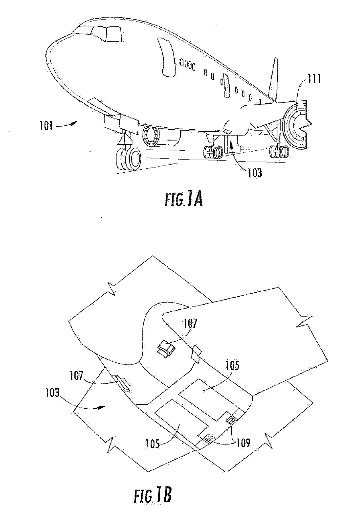
[0029]A detailed description of one or more embodiments of the disclosed apparatus and method are presented herein by way of exemplification and not limitation with reference to the Figures.

[0030]As shown in FIGS. 1A-1B, an aircraft 101 can include one or more bays 103 beneath a center wing box. The bay 103 can contain and / or support one or more components of the aircraft 101. For example, in some configurations, the aircraft 101 can include environmental control systems and / or fuel inerting systems within the bay 103. As shown in FIG. 1B, the bay 103 includes bay doors 105 that enable installation and access to one or more components (e.g., environmental control systems, fuel inerting systems, etc.). During operation of environmental control systems and / or fuel inerting systems of the aircraft 101, air that is external to the aircraft 101 can flow into one or more ram air inlets 107. The outside air may then be directed to various system components (e.g., environmental conditioning...


PUM

PropertyMeasurementUnit
Flow rateaaaaaaaaaa
Concentrationaaaaaaaaaa
Permeabilityaaaaaaaaaa

Abstract

A fuel tank inerting system is disclosed. In addition to a fuel tank, the system includes a catalytic reactor with an inlet, an outlet, a reactive flow path between the inlet and the outlet, and a catalyst on the reactive flow path. The catalytic reactor is arranged to receive fuel from the fuel tank and air from an air source, and to react the fuel and air along the reactive flow path to generate an inert gas. The system also includes an inert gas flow path from the catalytic reactor to the fuel tank. The system also includes (a) an air distributor in the catalytic reactor arranged to distribute air along the reactive flow path, or (b) non-uniform catalyst loading or non-uniform catalyst composition along the reactive flow path, or both (a) and (b).

Description

BACKGROUND[0001]The subject matter disclosed herein generally relates to fuel handling systems, and more particularly to fuel tank inerting systems such as used on aircraft.[0002]It is recognized that fuel vapors within fuel tanks become combustible in the presence of oxygen. An inerting system decreases the probability of combustion of flammable materials stored in a fuel tank by maintaining a chemically non-reactive or inert gas, such as nitrogen-enriched air, in the fuel tank vapor space, also known as ullage. Three elements are required to initiate and sustain combustion: an ignition source (e.g., heat), fuel, and oxygen. Combustion may be prevented by reducing any one of these three elements. If the presence of an ignition source cannot be prevented within a fuel tank, then the tank may be made inert by: 1) reducing the oxygen concentration, 2) reducing the fuel concentration of the ullage to below the lower explosive limit (LEL), or 3) increasing the fuel concentration to abov...

Claims


Application Information

Patent Timeline
IPC IPC(8): B64D37/32B01D53/86
CPCB64D37/32B01D53/8668B01D2257/7022B01J8/0492B01J8/0496B01J23/40B01J8/0257B01J8/0278B01J8/0285B01D53/8671B01D53/8687B01J8/0461B01D53/90B01D2251/102B01D2251/11B01D2251/208B01D2255/10B01D2255/1021B01D2255/1023B01D2255/2073B01D2255/903B01D2255/904B01D2256/22B01D2257/104B01D2257/70B01D2259/4575Y02T50/40B01J35/19
Inventor EMERSON, SEAN C.BOTROS, BARBARA BRENDADARDAS, ZISSIS A.SMITH, LANCE L.SURAWSKI, ERICTHIBAUD, CATHERINE
Owner HAMILTON SUNDSTRAND CORP