Detecting and predicting mechanical failure due to lubrication loss in machines and movable components

Active Publication Date: 2019-06-20
UNITED STATES OF AMERICA THE AS REPRESENTED BY THE SEC OF THE ARMY
View PDF9 Cites 3 Cited by
  • Summary
  • Abstract
  • Description
  • Claims
  • Application Information

AI Technical Summary

Benefits of technology

[0007]In view of the foregoing, an embodiment herein provides a method of detecting and predicting mechanical failure of movable components, the method comprising setting a predefined threshold gas concentration level in a substantially enclosed machine comprising a moveable component subjected to a loss-of-lubrication event capable of causing mechanical wear and failure, wherein the predefined threshold gas concentration level indica

Problems solved by technology

There are a number of sensors that are part of the lubrication system that could act as possible indicators for loss-of-lubrication in a rotorcraft gearbox, but their limited functionality generally makes them unable to provide the detailed information required to estimate machine operating life until total failure nor a gearbox's health during the event.
Unpressurized systems, however, often are not afforded an indicator beyond a sight glass, which cannot be monitored in many situations, or a temperature measurement, which may not provide a timely warning.
The temperature of the oil sump is collected and usually transmitted to the cockpit, but a loss of the lubricant renders this temperature meaningless until the housing to which it is attached increases in temperature, perhaps after the gearbox has already failed.
Attaching temperature sensors to the gearbox housing could provide some useful information on the health of the gearbox, however, this does not provide a real-time approach since there would be a delay equal to the time it takes for the heat generated at the failing gear and bearing contacts to be transmitted to the housing.
Using vibration measurements as an indicator for a loss-of-lub

Method used


Image

  • Detecting and predicting mechanical failure due to lubrication loss in machines and movable components
  • Detecting and predicting mechanical failure due to lubrication loss in machines and movable components
  • Detecting and predicting mechanical failure due to lubrication loss in machines and movable components

Examples


first embodiment

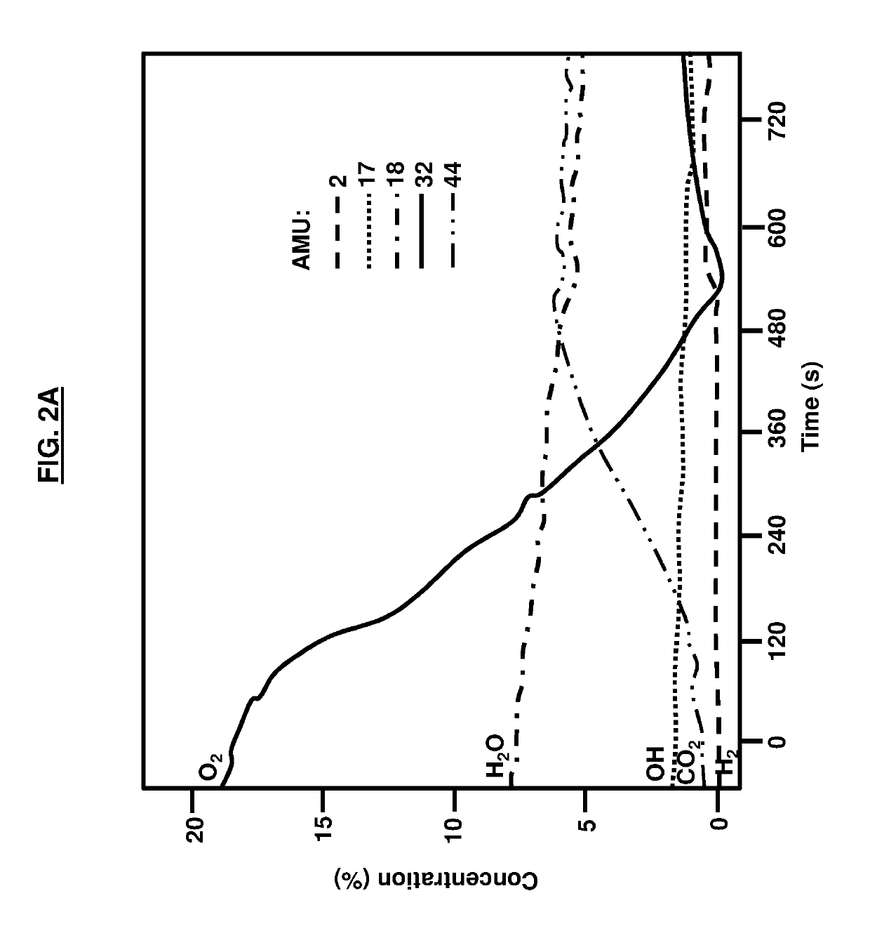
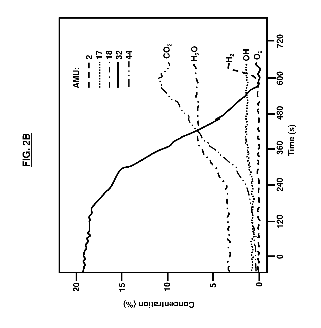
[0032]The embodiments herein provide for various methods to detect the loss-of-lubrication. In a method the amount of oxygen alone is used to detect the loss-of-lubrication. When a high speed mechanical contact is fully lubricated, the surface is largely protected from damage through hydrodynamic or elastohydrodynamic lubrication, in which a thin film of liquid lubricant separates and protects two solid surfaces from contact. If the surfaces come into contact due to inadequate lubrication, their high speed causes them to undergo rapid frictional heating, which results in oxidative wear for steel and many other metals. A decrease in the oxygen level indicates that oxidative wear has begun due to an interruption in the lubricant supply. Based upon a measured or sensed decrease in oxygen, a signal may be given that the lubricant supply has been interrupted and a loss-of-lubrication situation is occurring in the gearbox or enclosed machinery. The rise in the carbon dioxide level may al...

second embodiment

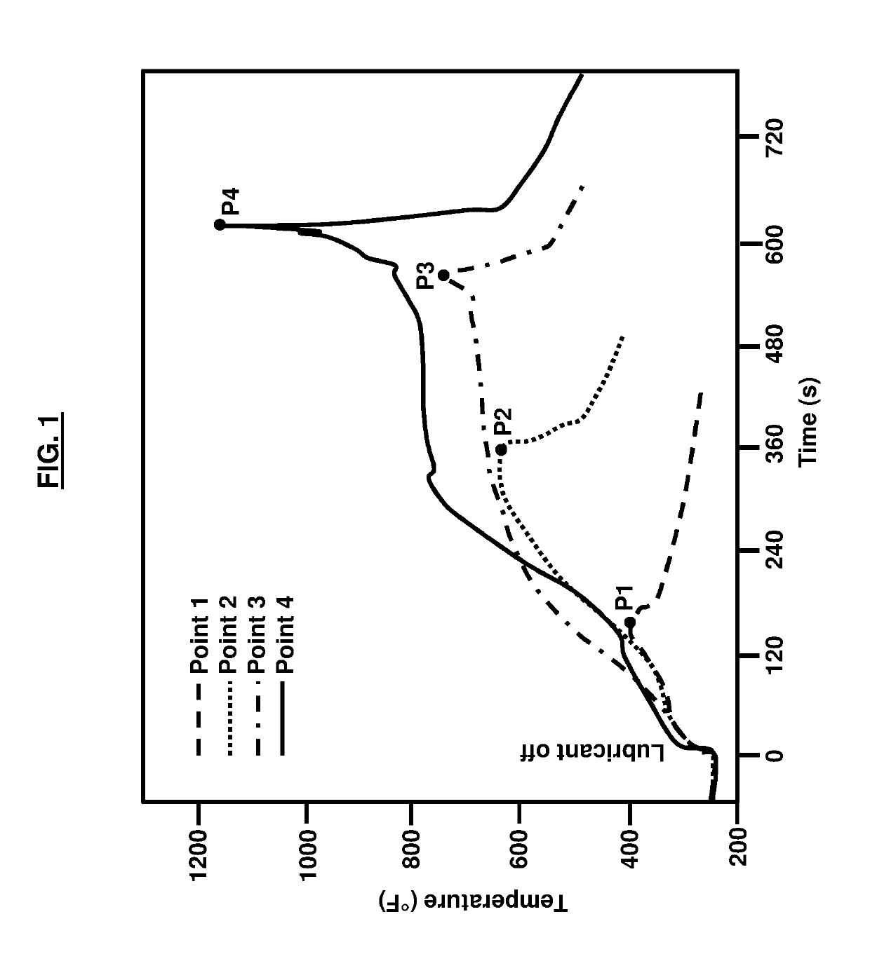
[0034]In a method the concentration of oxygen and its rate of decrease may be used to determine the state of damage, time to catastrophic failure, and imminence of failure, if further information has been gathered on an equivalent or identical mechanical system in a loss-of-lubrication test. The rate of decrease in oxygen corresponds to the different rates of increase in temperature, and hence to the different processes of damage that are occurring. The initially increasing rate of oxygen depletion corresponds to an expanding zone of oxidative wear, while the linear portion corresponds to a steady-state of oxidative wear. The linearity of the decrease in oxygen before thermal run-away lends itself to determining the time that its level will approach zero, which is when failure occurs. It can be seen for P3 and P4 that the slope of decrease is somewhat different, however its intercept with a pressure of zero corresponds to the beginning of thermal run-away. Alternatively, the concen...

third embodiment

[0038]In a method the ratio of concentrations of oxygen and carbon dioxide may be used to accurately predict the time to catastrophic failure and imminence of catastrophic failure. FIG. 4 shows the ratio of the normalized partial pressures CO2:O2 (masses 44 and 32 Atomic Mass Units, AMU) for experimental gear sets P3 and P4. The partial pressures are normalized to their initial value before lubrication is stopped. As the data shows, after an initial slower increase, the ratios for both experimental gear sets increase approximately linearly until an inflection occurs and the increase is greater.

[0039]This inflection occurs approximately 20-40 seconds before the onset of thermal run-away, which directly preludes full loss of torque. According to the embodiments herein, the inflection is used as a diagnostic warning that failure is imminent. Further, the ratio at which thermal run-away begins to occur is approximately the same for both experimental sets of gears P3 and P4 (the dotted ...


PUM


Abstract

Detecting the occurrence of loss of effective lubrication in high-speed machinery components is provided. The imminent catastrophic failure may be predicted when torque or power transfer is lost. An estimate of when failure will likely occur throughout the operation of the machinery may be determined as well as the damage state after the liquid lubrication supply has ended or becomes inadequate to lubricate the machinery components effectively. By monitoring the concentration of gas species and the rate of change in concentration of the gas in the gearbox or machinery enclosure after the supply of the primary lubricant ends, determinations may be made about the time to failure and the damage state. The determinations may be based on thermomechanical and chemical processes, on measurement of a baseline system, or by setting a threshold of expected change in gas concentration. These determinations may be transmitted for further decision making and response.

Description

GOVERNMENT INTEREST[0001]The embodiments described herein may be manufactured, used, and / or licensed by or for the United States Government without the payment of royalties thereon.BACKGROUNDTechnical Field[0002]The embodiments herein generally relate to monitoring techniques, and more particularly to monitoring lubrication loss in machines and other components.Description of the Related Art[0003]There are a number of sensors that are part of the lubrication system that could act as possible indicators for loss-of-lubrication in a rotorcraft gearbox, but their limited functionality generally makes them unable to provide the detailed information required to estimate machine operating life until total failure nor a gearbox's health during the event. For example, initial detection of lubricant loss in a gearbox typically is by the oil pressure sensor for pressurized systems and the signal is monitored in the cockpit. Unpressurized systems, however, often are not afforded an indicator b...

Claims


Application Information

Patent Timeline
IPC IPC(8): F16N29/04F16H57/04G07C5/08
CPCF16N29/04F16H57/0449G07C5/0816G07C5/0808B64C27/006F16N2260/02F16N2260/06F16N2210/12F16N2210/08B64D2045/0085B64C27/12
Inventor BERKEBILE, STEPHEN P.RADIL, KEVIN C.
Owner UNITED STATES OF AMERICA THE AS REPRESENTED BY THE SEC OF THE ARMY
Why Eureka
Try Eureka