Physical Quantity Sensor, Composite Sensor, Inertial Measurement Unit, Portable Electronic Apparatus, Electronic Apparatus, And Vehicle

Active Publication Date: 2019-06-20
SEIKO EPSON CORP
View PDF13 Cites 3 Cited by
  • Summary
  • Abstract
  • Description
  • Claims
  • Application Information

AI Technical Summary

Benefits of technology

[0036]In this application example, the attitude control unit (attitude controller) controls at least one system from among an engine system, a braking system, and a keyless entry syste

Problems solved by technology

However, when the sensor element described in JP-A-2009-175079 is to be manufactured by the dry etching technique described in JP-T-7-503815, if the shape pattern of each site of the sensor element is partly coarse and fine, the etching gas spreads unevenly, thus causing the cross-sectional shape of each site to vary.
This poses the problem of r

Method used


Image

  • Physical Quantity Sensor, Composite Sensor, Inertial Measurement Unit, Portable Electronic Apparatus, Electronic Apparatus, And Vehicle
  • Physical Quantity Sensor, Composite Sensor, Inertial Measurement Unit, Portable Electronic Apparatus, Electronic Apparatus, And Vehicle
  • Physical Quantity Sensor, Composite Sensor, Inertial Measurement Unit, Portable Electronic Apparatus, Electronic Apparatus, And Vehicle

Examples


Example

First Embodiment

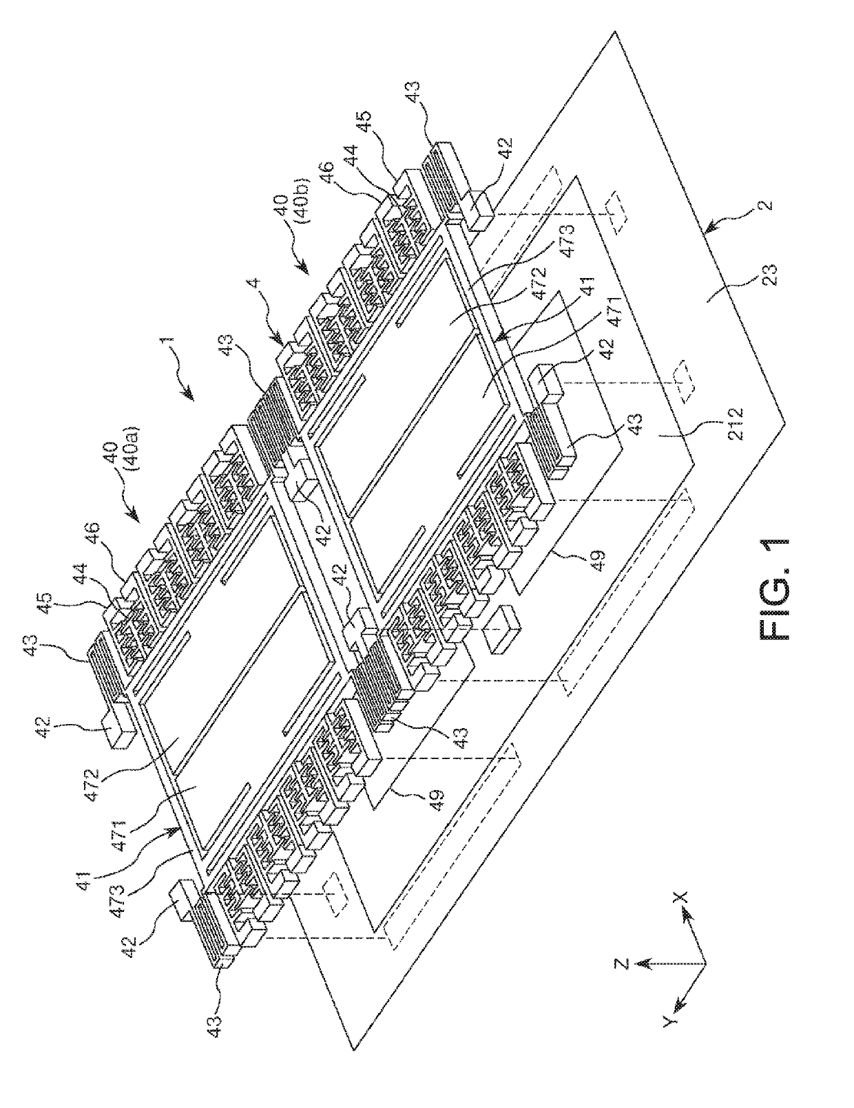
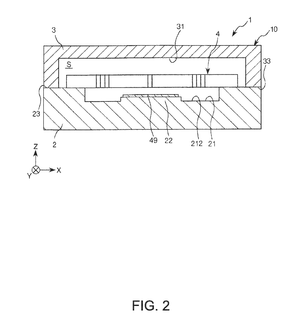
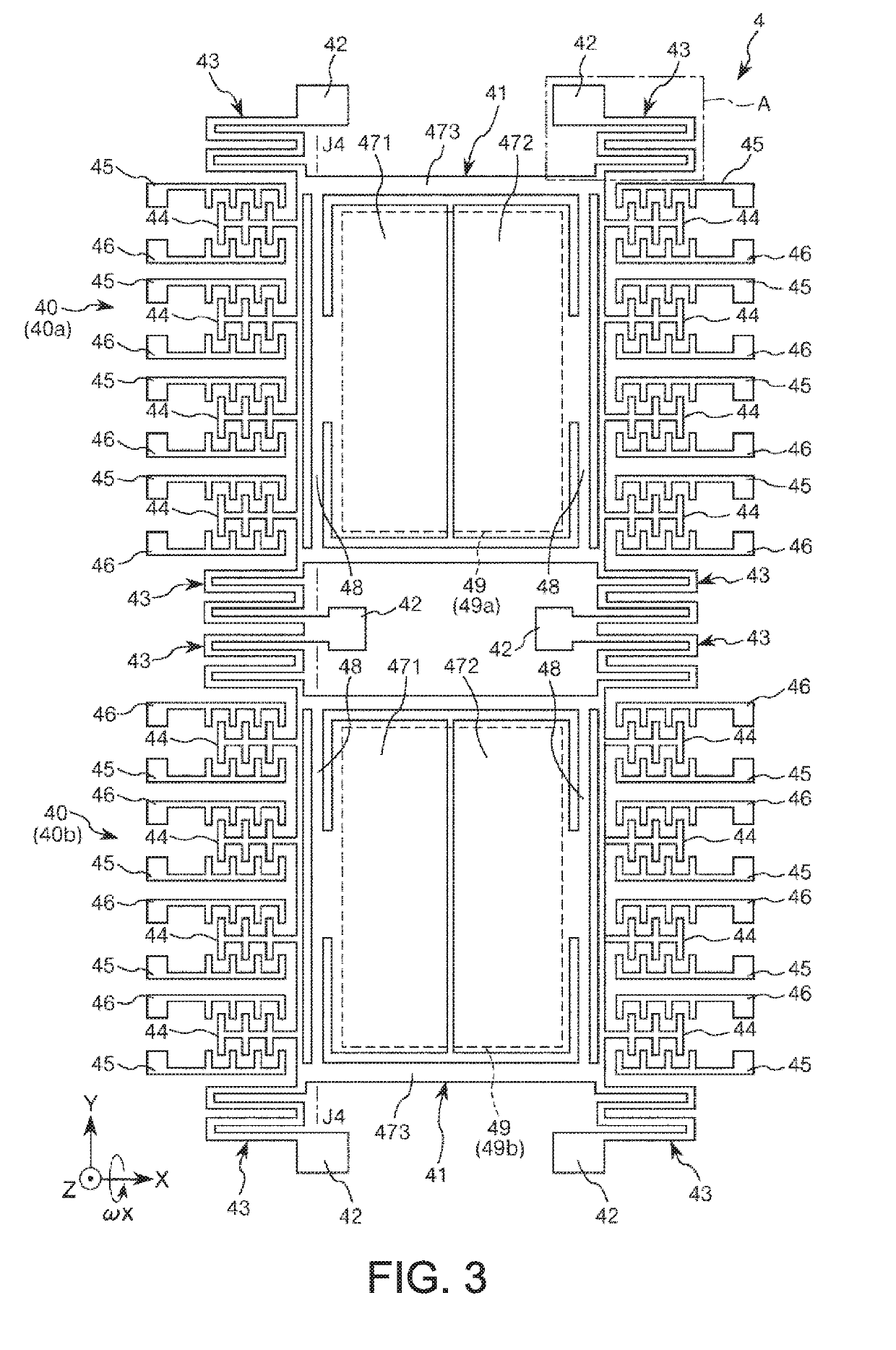
[0059]First, as an embodiment of the physical quantity sensor, a gyro sensor (angular velocity sensor) is described with reference to FIGS. 1, 2, and 3. FIG. 1 is a perspective view showing a schematic configuration of a gyro sensor (angular velocity sensor) according to a first embodiment of the physical quantity sensor. FIG. 2 is a cross-sectional view showing a schematic configuration of the gyro sensor shown in FIG. 1. FIG. 3 is a plan view schematically showing a gyro sensor element shown in FIG. 1. FIG. 1 schematically shows a substrate (base) and does not show a lid. In the following description of each embodiment of the physical quantity sensor below, an X-axis (third axis), a Y-axis (first axis), and a Z-axis (second axis) are provided as three axes orthogonal to each other. A direction along the X-axis is also referred to as “X-axis direction”. A direction along the Y-axis is also referred to as “Y-axis direction”. A direction along the Z-axis is also refer...

Example

Second Embodiment

[0115]Next, a second embodiment of the physical quantity sensor will be described with reference to FIGS. 7 and 8. FIG. 7 is a plan view showing a schematic configuration of a gyro sensor according to the second embodiment of the physical quantity sensor. FIG. 8 is a plan view schematically showing a part (part C) of an elastic part shown in FIG. 7. In the description below, three axes orthogonal to each other, that is, X-axis, Y-axis, and Z-axis similar to those in the first embodiment are used. Also, in the description below, differences from the first embodiment are mainly described and similar matters are not described further in detail.

[0116]As shown in FIGS. 7 and 8, a gyro sensor 1A according to the second embodiment is an angular velocity sensor that can detect an angular velocity about the X-axis, as in the first embodiment. This gyro sensor 1A has a gyro sensor element (angular velocity sensor element) 505 as a sensor element, and a package (not illustrate...

Example

Third Embodiment

[0133]Next, a third embodiment of the physical quantity sensor will be described with reference to FIGS. 9 and 10. FIG. 9 is a plan view showing a schematic configuration of a gyro sensor according to the third embodiment of the physical quantity sensor. FIG. 10 is a plan view schematically showing a part (part F) of an elastic part shown in FIG. 9. In the description below, three axes orthogonal to each other, that is, X-axis, Y-axis, and Z-axis similar to those in the first embodiment are used. Also, in the description below, differences from the first embodiment are mainly described and similar matters are not described further in detail.

[0134]As shown in FIGS. 9 and 10, a gyro sensor 1B according to the third embodiment is an angular velocity sensor that can detect an angular velocity about the X-axis or the Y-axis. This gyro sensor 1B has a gyro sensor element (angular velocity sensor element) 605 as a sensor element, and a package (not illustrated) accommodatin...


PUM


Abstract

A gyro sensor includes: a spring having an inner span beam connected to an outer span beam via a turnaround beam; and a fixed driver that laterally faces the outer beam. A first beam is provided to the structure side of the outer beam so as to face the outer beam. T1 is a width of a space between the outer beam and the structure, T2 is a width of a space between the inner and outer beams, and T2<T1.

Description

BACKGROUND1. Technical Field[0001]The present invention relates to a physical quantity sensor, a composite sensor, an inertial measurement unit, a portable electronic apparatus, an electronic apparatus, and a vehicle.2. Related Art[0002]Recently, as an example of a physical quantity sensor, a gyro sensor which uses a gyro sensor element utilizing silicon MEMS (micro-electromechanical system) technology has been developed. Among physical quantity sensors, the gyro sensor, which detects an angular velocity, is quickly coming into widespread use, for example, for the motion sensing function of a game machine or the like.[0003]As such a gyro sensor, for example, JP-A-2009-175079 discloses a sensor element that forms an angular velocity sensor. The sensor element has a support substrate, a fixed part fixed to the support substrate, a vibrator supported to the fixed part via an elastic beam (support beam), a movable comb-like electrode provided on the vibrator, and a fixed comb-like elect...

Claims


Application Information

Patent Timeline
IPC IPC(8): G01P15/14G01P15/08G01C19/5783
CPCG01P15/14G01P15/0802G01C19/5783G05D1/027G01P9/04G01C19/5712B81B3/0067B81B2201/0242G01P15/18G01C19/5747G01C19/5733
Inventor TAKIZAWA, TERUO
Owner SEIKO EPSON CORP
Why Eureka
Try Eureka