A Parallel Optical Fiber Angled Coupling Component

a technology of parallel optical fibers and coupling components, applied in the field of optical elements, can solve the problems of time difference and inter-modal dispersion, and achieve the effects of increasing the transmission distance, reducing inter-modal dispersion, and increasing the transmission distan

Active Publication Date: 2019-06-27
SENKO ADVANCED COMPONENTS
View PDF18 Cites 3 Cited by
  • Summary
  • Abstract
  • Description
  • Claims
  • Application Information

AI Technical Summary

Benefits of technology

[0014]A large number of guided modes can be transmitted in the optical fiber, and the guided modes that can be excited and the optical power proportion of each excited guided mode depend on the distribution of the incident light field. For example, compared with normal incidence from the center of the optical fiber, if the laser beam is normally incident upon the end face of the optical fiber at a certain centrifugal distance, the combination of excited guided modes and the optical power proportion of each guided mode are completely different, resulting in different inter-modal dispersion values. In optical fiber applications, there is a restricted mode launch method, that is, the laser beam is normally incident upon the end face of the optical fiber at a certain centrifugal distance, and the resulting inter-modal dispersion will be much less than that of normal incidence from the center of the optical fiber, thereby increasing the optical signal transmission distance in the optical fiber. If the light beam is made incident upon the center of the optical fiber at a certain inclination, the same effect can be achieved, that is, reduction in inter-modal dispersion and increase in transmission distance.
[0015]In the existing parallel optical fiber angled coupling components, the end face of the optical fiber is polished into a bevel with an inclination of 45°, so that the optical signal can achieve 90° angled coupling between the laser array and the optical fiber. After the laser beam is reflected by the 45° bevel, it is incident on the center of the optical fiber along the horizontal direction. Then, a set of guided modes will be excited, but the transmission distance is restricted due to the larger inter-modal dispersion. This invention proposes that the end face of the optical fiber is polished into a bevel with an inclination of 42.

Problems solved by technology

The light wave of each guided mode has a different transmission speed in the optical fiber, resulting in inter-modal dispersion.
Due to the influence of inter-modal dispersion, in the same optical pulse, the light energy components carried by different guided modes cannot reach t

Method used


Image

  • A Parallel Optical Fiber Angled Coupling Component
  • A Parallel Optical Fiber Angled Coupling Component

Examples


Embodiment Construction

[0024]The technical solution of the patent is further described in detail below in combination with the specific embodiments.

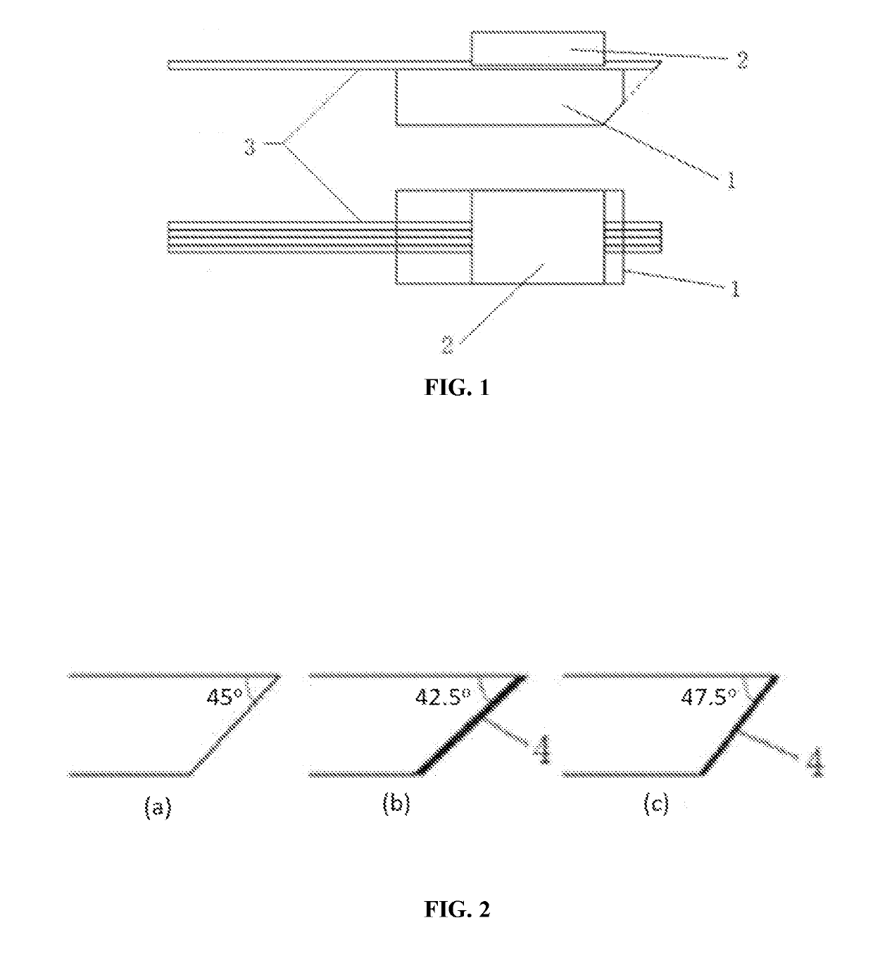
[0025]The structure of a parallel optical fiber angled coupling component is shown in FIG. 1, comprising a positioning substrate 1, a cover plate 2 and a plurality of optical fibers 3. The optical fibers 3 are pressed into a plurality of positioning grooves on the positioning substrate 1 by the cover plate 2 and fixed with glue. To realize angled coupling of the optical signal from the laser to the optical fiber, the end surface of the optical fiber 3 is polished into a bevel with a certain inclination, as shown in FIG. 2. The existing technical solution is that the bevel inclination of the optical fiber is 45°, as shown in FIG. 2(a); the technical solution proposed by this invention is that the bevel inclination of the optical fiber 3 is 42.5° or 47.5°, as shown in FIGS. 2(b) and 2(c). In the existing technical solution, no reflective film is coated on the be...


PUM


Abstract

A parallel optical fiber angled coupling component, which is used for parallel coupling of optical signal between the optical fiber array and the laser array, comprises an optical fiber positioning substrate, a cover plate and a plurality of optical fibers. The end face of the optical fiber is polished into a bevel with an inclination of 42.5° or 47.5°, and the bevel of the optical fiber is coated with a metal reflective film. This invention has the following beneficial effects: The end face of the optical fiber is polished into a bevel with an inclination of 42.5° or 47.5° to reduce inter-modal dispersion and increase the transmission distance of the optical signal in the subsequent optical fiber; the bevel of the optical fiber is coated with a metal reflective film, so as to ensure high reflectivity even if the bevel of the optical fiber is covered with glue.

Description

CROSS-REFERENCE TO RELATED APPLICATIONS[0001]The present application is a national phase application of PCT / CN2017 / 089552 which claims priority to Chinese Patent Application No. 201620634614.X filed Jun. 24, 2016, the disclosure of which is incorporated by reference herein.COPYRIGHT NOTICE[0002]A portion of the disclosure of this patent document contains material, which is subject to copyright protection. The copyright owner has no objection to the facsimile reproduction by anyone of the patent document or the patent disclosure, as it appears in the Patent and Trademark Office patent file or records, but otherwise reserves all copyright rights whatsoever.FIELD OF THE INVENTION[0003]This invention relates to an optical element used in the field of optical fiber technology, particularly to an optical fiber angled coupling component used in a parallel optical fiber transmission module.BACKGROUND[0004]With the advent of the big data era, large data centers have seen rapid growth. Data c...

Claims


Application Information

Patent Timeline
IPC IPC(8): G02B6/38G02B6/42G02B6/43
CPCG02B6/3822G02B6/425G02B6/43G02B6/3829G02B6/4214G02B6/4243
Inventor YANG, KAIFA
Owner SENKO ADVANCED COMPONENTS
Why Eureka
Try Eureka