
Inertial water column wave energy converter

Active Publication Date: 2019-07-04
LONE GULL HLDG LTD
View PDF75 Cites 3 Cited by
  • Summary
  • Abstract
  • Description
  • Claims
  • Application Information

AI Technical Summary

Benefits of technology

The patent describes a device that uses an air turbine placed in a narrow section of a water tube to increase the speed of the air flow and capture more power from it. The device also includes a flexible material that allows the tube to bend while maintaining its shape and a limit on how much it can bend. This helps to prevent the tube from collapsing while still allowing it to bend and flex.

Problems solved by technology

Few if any inventions of the prior art have permitted the capture and beneficial use of this energy in a manner that is both economical and robust to ocean storms.

Method used


Image

  • Inertial water column wave energy converter
  • Inertial water column wave energy converter
  • Inertial water column wave energy converter

Examples


embodiment 100

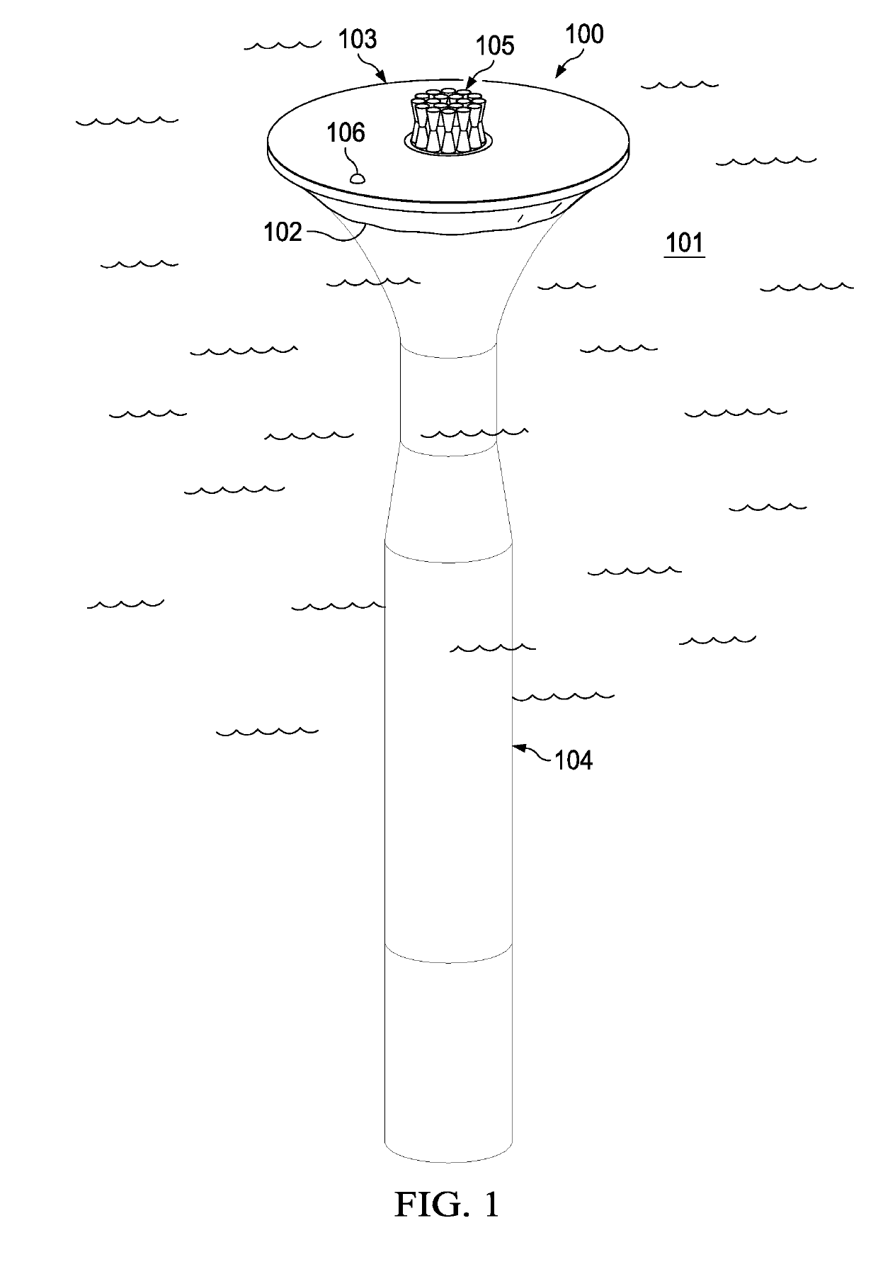
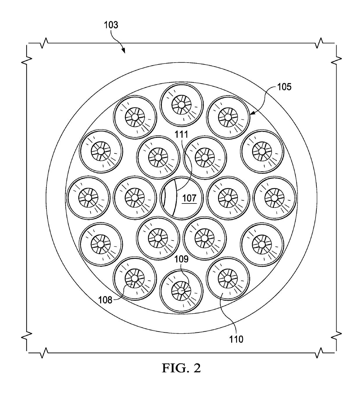
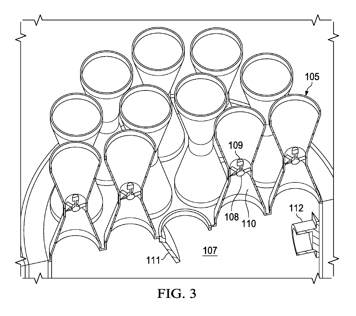
[0248]FIG. 1 shows a perspective view of an embodiment of the current disclosure. The illustrated embodiment 100 is of the type described above in the section entitled, “Hyper-Pressurized Air Pocket and Water Hammer.” Especially when water within the embodiment's water column tube 104 is rising, over pressurized air within the water column tube is driven out through a plurality of turbines 105 positioned in the throats of venturi shrouds. Especially when water within the embodiment's water column tube 104 is falling, under pressurized air within the water column tube is supplemented and / or equilibrated through the admission of ambient outside air through a one-way valve positioned among the venturi shrouds 105 at the top of the embodiment.

[0249]Inertial water column wave energy convertor (IWC) 100 is floating in a body of water 101 with waterline 102. IWC 100 is comprised of two primary components, flotation structure 103 and water column tube 104. Flotation structure 103 has a conc...

embodiment 200

[0291]IWC 400 is floating in a body of water 401 with waterline 402. IWC 400 is comprised of a flotation structure 403 and four water column tubes, e.g., 404. Each water column tube 404 is similar in construction and function to the water column tube 204 incorporated within embodiment 200 illustrated in FIGS. 7-11. Flotation structure 403 has a polygonal profile and is intersected by waterline 402. Water column tubes 404 are braced together with structural members 405, arranged to form a truss. Water entering or exiting the bottom of each water column tube 404 must also pass through a respective nozzle 406, which constricts the hollow central chamber of water column tubes 404 to a smaller diameter at their bottoms. The larger upper diameter and smaller lower diameters of nozzles 406 acts to accelerate water flow exiting the water column tube. The operation of this embodiment with respect to power-generation is similar to previous embodiments.

[0292]Pneumatic power take-off assemblies...

embodiment 400

[0293]The two other PTOs, e.g., 407B, are installed horizontally on directional flow mounts, e.g., 409. The directional flow mounts 409 redirect vertical air flow exiting from the respective water column tubes 404 into a horizontal direction through the respective PTOs, e.g., 407B. When air escapes from the horizontal PTO modules 407B, a thrust is produced, which can accelerate IWC 400. Directional flow mounts 409 are able to rotate about a vertical axis running through the center of the respective water column tube 404 upon which they are installed. This allows thrust produced by air exiting PTO modules 407B to be vectored (i.e. the thrust produced can be directed to produce linear and / or rotational acceleration of IWC 400) and the embodiment 400 to be steered, e.g., in a desirable direction and / or toward a desirable destination.

[0294]Junction computation box 410 is installed on, and / or attached to, the flotation module 403 and may contain a variety of electronic equipment, includi...


PUM


Abstract

Disclosed is a novel device that converts some of the power in ocean waves into electrical power or other means of performing useful work. One or more tubes are arranged so that when the device is in position in a body of water, the tubes are oriented vertically with one end positioned proximate to and / or above the surface of the body of water on which the device floats, and with the other end positioned below the surface of that body of water. In some embodiments, through a differential restriction on the flow of air in and out of an upper end of the tube, the average height of the water inside the tube is different from the average height of the water outside the tube. In some embodiments, a hollow void inside a flotation structure of the embodiment is filled with water to contribute significant mass to the embodiment and increase the momentum associated with its vertical oscillations. Additional elements of the present disclosure include features that protect the device from damage during periods of large waves, and facilitate the powering and cooling of computers and / or other electronic equipment operated therein.

Description

CROSS-REFERENCES TO RELATED APPLICATIONS[0001]This application claims priority from U.S. Ser. No. 62 / 613,260, filed Jan. 3, 2018 and U.S. Ser. No. 62 / 614,419, filed Jan. 7, 2018, incorporated by reference in their entirety.BACKGROUND[0002]Very large amounts of energy are available in the waves that traverse the surface of the world's oceans. Few if any inventions of the prior art have permitted the capture and beneficial use of this energy in a manner that is both economical and robust to ocean storms.[0003]The disclosed wave energy converter is both economical and robust, requiring a relative economy of structural material and having few moving parts.SUMMARY OF THE INVENTION[0004]The present invention is a floating wave energy converter that converts wave motion into electrical power when it oscillates vertically in response to the passage of ocean waves. Vertical oscillations of the wave energy converter structure can be out of phase with those of a volume of water located inside ...

Claims


Application Information

Patent Timeline
IPC IPC(8): F03B13/24H02K7/18H02K5/04
CPCF03B13/24H02K7/183H02K5/04F03B13/142F05B2240/133F05B2240/40F05B2240/93F05B2240/95F05B2250/141F05B2270/18Y02E10/30Y02E10/72
Inventor SHELDON-COULSON, GARTH ALEXANDERPLACE, DANIEL WILLIAMMOFFAT, BRIAN LEE
Owner LONE GULL HLDG LTD
Learn More