RGB wavefront sensor for turbulence mitigation

a wavefront sensor and wavefront technology, applied in the field of optical systems, can solve the problems of poor image improvement algorithm, poor performance of optical remote sensing technology, atmospheric turbulence-induced degradation, etc., and achieve the effect of improving severely degraded images

Active Publication Date: 2019-07-11
MISSION SUPPORT & TEST SERVICES LLC
View PDF2 Cites 5 Cited by
  • Summary
  • Abstract
  • Description
  • Claims
  • Application Information

AI Technical Summary

Benefits of technology

[0010]Disclosed is a compact adaptive optics system for long-range horizontal paths that improves severely degraded images that includes an RGB wavefront sensor that allows the measurement of the phase of the wavefront errors without the need for a guidestar (laser or other coherent source). In one embodiment, the disclosed system uses a Hartmann mask (filter) composed of three distinct colors that correspond to the three colors in a typical color detector Bayer mask. Focus errors associated with turbulence show up as image shifts in the three distinct color images. Exploiting the shifts and using the statistics of turbulen

Problems solved by technology

The major limitation on performance of optical remote sensing technologies is atmospheric turbulence-induced degradation, especially in horizontal ISR (intelligence, surveillance and reconnaissance) applications at long range.
While algorithms exist for turbulence mitigation, under extreme turbulence, little or no high spatial frequency content remains and these algorithms will not work for image improvement.
Atmospheric turbulence-induced image degradation presents a significant problem in extended range surveillance and signal processing because, in many applications, these effects are more restrictive to viewing resolution than the diffraction limit.
Atmospheric effects linked to turbulence reduce the ability to make remote sensing measurements because these effects add spatial and spectra

Method used


Image

  • RGB wavefront sensor for turbulence mitigation
  • RGB wavefront sensor for turbulence mitigation
  • RGB wavefront sensor for turbulence mitigation

Examples


Embodiment Construction

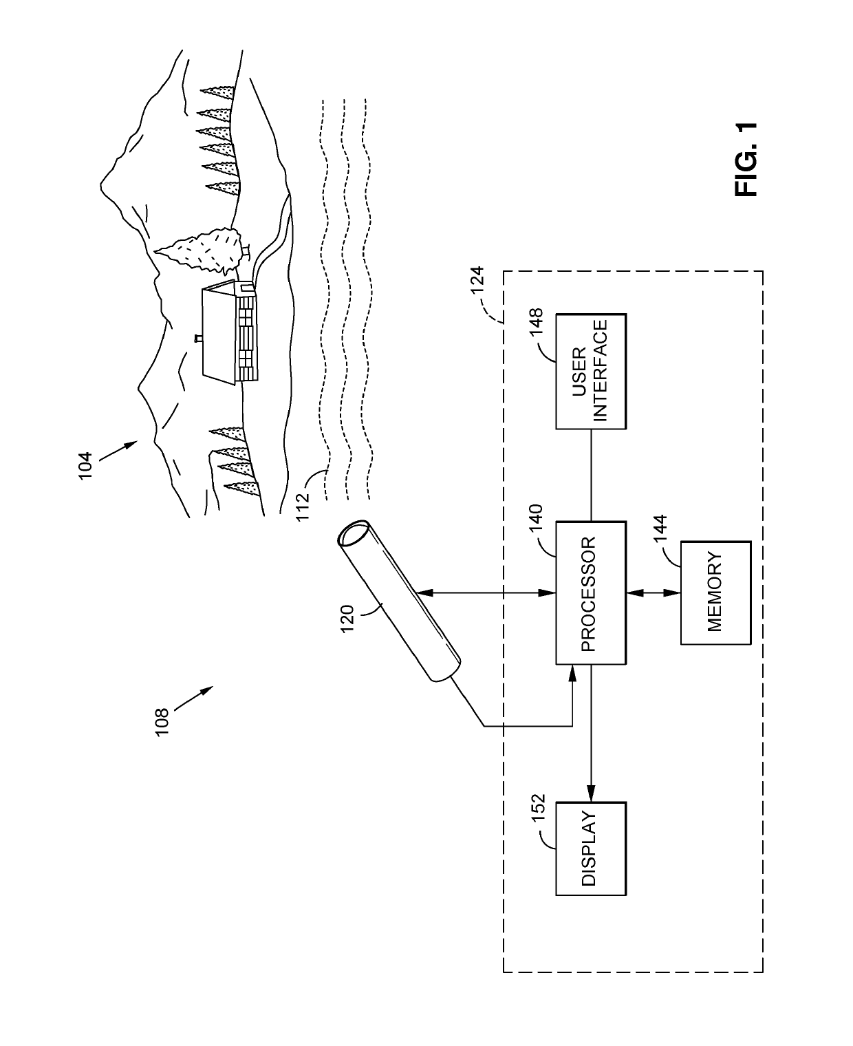
[0039]FIG. 1 is a block diagram of the innovation in an exemplary environment of use. This is but one possible example environment of use and system. It is contemplated that other embodiments and environments of use are possible. As shown, a distant scene 104 is presented for observation over a generally horizontal path. The reason for observation may vary by application but may range from the following applications: forestry, police, search and rescue, military, surveillance, commercial monitoring, farming, ranching, marine environments, or any other use or environment needing long range imaging of a distant scene.

[0040]Proposed and disclosed is a compact AO system for long-range horizontal paths that improves severely degraded images. Located remote from the scene 104 of interest is an imaging system 108. Between the imaging system 108 and the remote scene 104 is a distance over which turbulence 112 is present. As is understood in the art, turbulence 112 disrupts the light rays re...


PUM


Abstract

A compact adaptive optics system for long-range horizontal paths imaging that improves degraded images. The system uses a filter that corresponds to the three colors in a typical color detector element, one or more optic elements, a deformable mirror, and a detector. Focus errors, due to turbulence, in the image recorded by the detector element show up as image shifts in the three distinct color images. The shifts and statistics of these shifts between these simultaneous images are used to create control signals for the deformable mirror resulting in a compact adaptive optic system for horizontal paths without need for a point source located at the distance scene being imaged. Analysis of the relative pixel shifts in various regions of the image provides third order statistics revealing tip/tilt and additional Zernikes modes that are used to control a deformable mirror without the need for a guide star/point-source.

Description

2. PRIORITY CLAIM[0001]This application claims priority to and the benefit of U.S. Provisional Application 62 / 609,204 titled RGB WAVEFRONT SENSOR FOR TURBULENCE MITIGATION and filed on Dec. 21, 2017.1. GOVERNMENT STATEMENT[0002]This invention was made with government support under Contract No. DE-NA0003624 and was awarded by the U.S. Department of Energy, National Nuclear Security Administration. The government has certain rights in the invention.3. FIELD OF THE INVENTION[0003]The invention relates to optic systems and in particular to a method and system for using an RGB wavefront sensor for turbulence mitigation.4. RELATED ART[0004]The major limitation on performance of optical remote sensing technologies is atmospheric turbulence-induced degradation, especially in horizontal ISR (intelligence, surveillance and reconnaissance) applications at long range. While algorithms exist for turbulence mitigation, under extreme turbulence, little or no high spatial frequency content remains ...

Claims


Application Information

Patent Timeline
IPC IPC(8): G02B27/00H04N9/04H04N5/357G02B26/06G06T7/00G01J9/00
CPCG02B27/0068H04N9/0455H04N5/357G02B26/06G06T7/0002G01J9/00G06T2207/10032G06T2207/10024G06T2207/10016G01J2009/002G02B27/017G02B2027/0112G02B2027/011G02B2027/0138G02B2027/014G01J3/46G01J3/51H04N25/11H04N25/60
Inventor O'NEILL, MARY D.TERRY, DAVID
Owner MISSION SUPPORT & TEST SERVICES LLC
Why Eureka
Try Eureka