Storage battery cooling control device and storage battery cooling control method

a storage battery and control device technology, applied in secondary cells, battery servicing/maintenance, solar power generation devices and wind power generation devices, etc., can solve the problems of reducing the life of storage batteries, reducing the cooling efficiency of storage batteries, and reducing the heat generation of storage batteries due to joule heat. , to achieve the effect of preventing the deterioration of storage batteries, reducing the heat generation of storage batteries, and highly efficient cooling of storage batteries

Active Publication Date: 2019-08-01
MITSUBISHI ELECTRIC CORP
View PDF0 Cites 8 Cited by
  • Summary
  • Abstract
  • Description
  • Claims
  • Application Information

AI Technical Summary

Benefits of technology

[0016]According to the embodiments of the present invention, a configuration is included in which discharge to the cooling device while the storage battery is discharging a large amount of current to the external power source is limited by setting a cooling power threshold. Heat generation of the storage battery due to Joule heat can accordingly be reduced, which makes highly efficient cooling of the storage battery possible as well as the prevention of storage battery deterioration due to heavy load. The embodiments of the present invention also include a configuration in which the storage battery is cooled without limiting the current charged from and discharged to the external power source, by controlling the power of the cooling device. The ability to stabilize system power is accordingly high.
[0017]It is consequently possible to provide the storage battery cooling control device and the storage battery cooling control method in which the ability to stabilize system power is kept high while preventing high temperature and heavy load from cutting short the life span of the storage battery by efficiently cooling the storage battery with the cooling device.

Problems solved by technology

Solar power generation devices and wind power generation devices, however, are unstable power sources.
The storage battery generates heat while charging / discharging, and a rise in storage battery temperature markedly cuts short the life span of the storage battery.

Method used


Image

  • Storage battery cooling control device and storage battery cooling control method
  • Storage battery cooling control device and storage battery cooling control method
  • Storage battery cooling control device and storage battery cooling control method

Examples


first embodiment

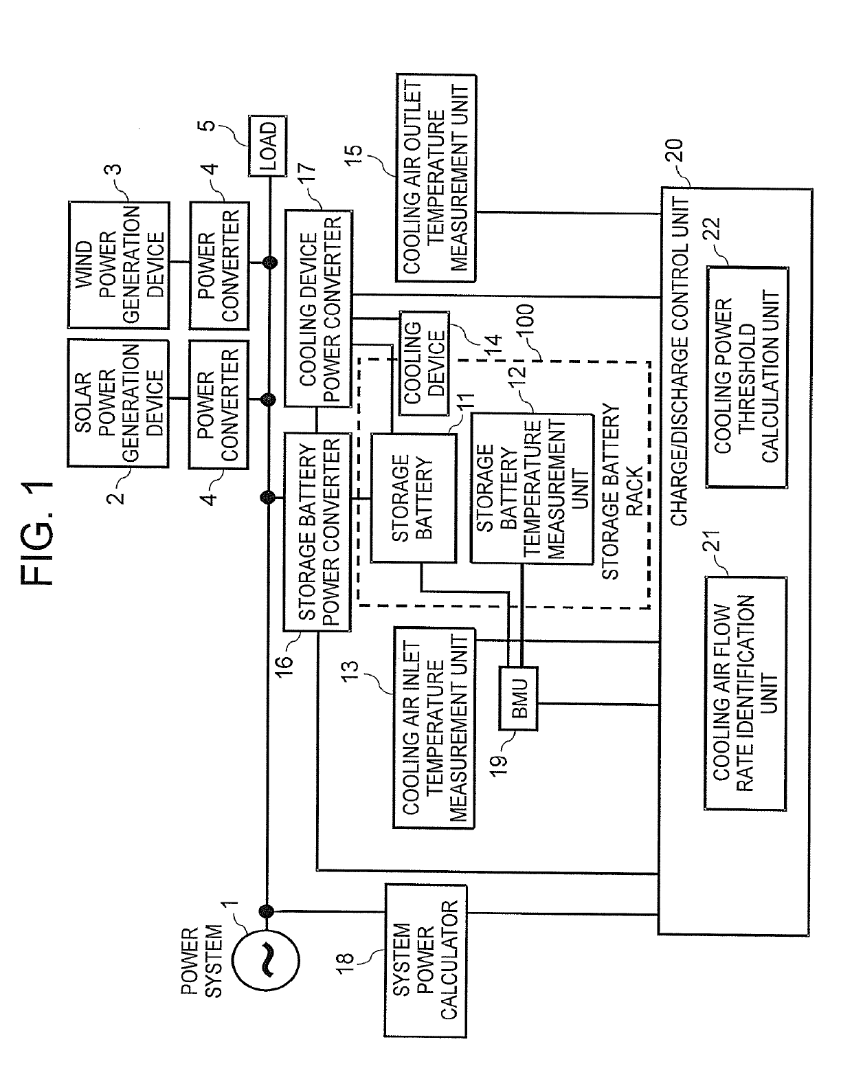
[0031]FIG. 1 is a diagram for illustrating the overall configuration of a storage battery system in which a storage battery cooling control device according to a first embodiment of the present invention is included. The description of the first embodiment takes as an example a storage battery system installed in a power plant, a substation, or a similar facility to execute charging / discharging for the purpose of suppressing power fluctuation caused in a power system 1 by a solar power generation device 2, a wind power generation device 3, a load 5, or other components.

[0032]In FIG. 1, each of the solar power generation device 2 and the wind power generation device 3 is connected to the power system 1 via a power converter 4. The mode illustrated in FIG. 1 is merely an example, and the storage battery system may have modes for other uses.

[0033]The storage battery system illustrated in FIG. 1 includes a storage battery 11, a storage battery temperature measurement unit 12, a cooling ...

second embodiment

[0103]A second embodiment of the present invention deals with a case in which charge is controlled with a charge current threshold taken into consideration. The second embodiment also deals with a case in which discharge is controlled with the cooling power threshold taken into consideration by a method different from the one in the first embodiment.

[0104]The method of determining a charge current threshold in the second embodiment is described first. The EMU 19 first determines an SOC range of the storage battery 11. The SOC is a charging rate indicating the remaining capacity of the storage battery 11, and is expressed by a numerical value within a range of from 0% to 100%. An SOC of 0% means a completely discharged state, and an SOC of 100% means a fully charged state.

[0105]The SOC is estimated by a commonly known current integration method, an OCV estimation method (OCV stands for open circuit voltage, which is the battery voltage), or a similar method. However, the method of es...


PUM

PropertyMeasurementUnit
power calculatoraaaaaaaaaa
voltageaaaaaaaaaa
currentaaaaaaaaaa

Abstract

A storage battery cooling control device includes a system power calculator (18) configured to calculate power of an external power source as power information, and a charge/discharge control unit (20) configured to perform charge/discharge control of a storage battery based on the power information, and to perform power control of a cooling device by distributing power to the cooling device within a cooling power threshold, which is determined so that a heat generation increment of the storage battery is equal to or less than a heat exhaust increment of the cooling device calculated from a cooling air flow rate.

Description

TECHNICAL FIELD[0001]The present invention relates to a storage battery cooling control device and a storage battery cooling control method in which cooling control is applied to a storage battery system configured to charge from and discharge to a power system.BACKGROUND ART[0002]A large-scale introduction of power generation devices using natural energy, for example, solar power generation devices and wind power generation devices, to a power system is expected. Solar power generation devices and wind power generation devices, however, are unstable power sources. It is therefore becoming common to connect a storage battery to the power system in order to suppress power fluctuation.[0003]The storage battery generates heat while charging / discharging, and a rise in storage battery temperature markedly cuts short the life span of the storage battery. The related art in which a cooling fan for cooling the storage battery is included and the related art in which a charge current and a d...

Claims


Application Information

Patent Timeline
Patent Type & Authority Applications(United States)
IPC IPC(8): H01M10/613H01M10/44H01M10/48H01M10/627H01M10/633H01M10/6557H01M10/6563H02J7/00
CPCH01M10/613H01M10/443H01M10/486H01M10/627H01M10/633H01M10/6557H01M10/6563H02J7/0068H02J7/0029H02J7/0047H01M2220/10H02J3/32H02J3/383H02J3/386H02J2007/005H01M10/44H01M10/48H02J7/00Y02E10/56Y02E10/76Y02E60/10H02J7/0048H02J3/38
Inventor IDA, TAKAHITOOGASAWARA, KEISUKE
Owner MITSUBISHI ELECTRIC CORP
Why Eureka
Try Eureka