Hybrid propellant electromagnetic gun system

a propellant electromagnetic and gun system technology, applied in the field of hybrid propellant electromagnetic gun systems, can solve the problems of limited propellant mass, single or multiple windings of coils, insufficient acceleration to provide large acceleration, and limited final velocity of projectiles, etc., to achieve increased projectile velocity, high blast level, and more energetic propellant

Active Publication Date: 2016-11-24
ENIG ASSOCS
View PDF3 Cites 8 Cited by
  • Summary
  • Abstract
  • Description
  • Claims
  • Application Information

AI Technical Summary

Benefits of technology

[0013]The firing of conventional propellant guns produces a large flash of light and high blast overpressure just as the projectile exits the muzzle. These aspects have consequences in terms of a signature that can give away the position of the gun and hazardous hearing and lung response to such high levels of blast. Past approaches to increase projectile velocity by some 10 to 15 percent by propellant guns have used extended barrel length, used more propellant, and used more energetic propellant. While the projectile is accelerated at a higher rate leading to higher muzzle velocity, large amounts of burning propellant are ejected at the muzzle. Thus, greater intensity and duration of flash occurs and higher blast pressure exits the gun. Modern guns often are less efficient, have higher flash signatures, and create far more hazardous blast environments for the gun crew. The present invention provides means to reduce both effects. The first means is that higher projectile velocity is obtained using electromagnetic energy rather than more propellant and more energetic propellants, although such propellant could be used. A second means comes from release of combustion gaseous by venting them to the gun exterior after the projectile has been fully accelerated by combustion pressures but before the projectile enters the acceleration coils. The blast is reduced initially from use of less propellant and venting reduces high-pressure blast that exits the gun barrel muzzle. Muzzle flash is reduced since less burning propellant is ejected at the muzzle.
[0014]An advantage of the present invention is that electrical energy is used to boost the projectile from a given velocity to higher velocity rather than accelerating the projectile from an initial rest position. The referenced Sandia National Laboratory's coilgun accelerates a 50mm diameter projectile of 247 grams from rest to 314 meter per second while designs have been put in place to obtain 1000 meter per second. The present invention, for example, accelerates the projectile to 1400 meters per second using standard propellants and uses electrical energy to boost the projectile velocity from 1400 meters per second to a velocity of the order of 2400 meters per second. Accelerating a moving projectile reduces the time that the projectile spends under the influence of each coil stage, which reduces Joule heating and provides higher overall efficiency in converting electrical energy to kinetic energy. Assume a 10 kilogram projectile and a 40 kilogram driver mass are accelerated by propellant to 1400 meters per second. Then the projectile is boosted from its initial velocity of 1400 to 2400 meters per second, for example, using 19 megaJoules of electrical energy. The driver initially has 39 megaJoules of energy at 1400 meters per second and gives up this energy when brought to zero velocity. Then with decelerator and accelerator systems having 0.7 conversion efficiencies for an overall combined electromagnetic energy conversion efficiency of 0.5, there are 19.5 megaJoules of energy available to further accelerate the projectile to 2400 meters per second.
[0015]In the past, coil guns have been designed, built, and tested. The most notable groups examining coil guns include Sandia National Laboratory in Albuquerque, New Mexico, as disclosed in: “SLINGSHOT—A Coilgun Design Code,” Sandia National Laboratories Report, SAND2001-1780, B, M, Marder, 2001. Sandia National Laboratory also has contrasted the merits of coilgun and railgun for launching mortars as disclosed in: “EM Mortar Technology Development for Indirect Fire,” SAND ADA481646, B. N. Thurman et al, 1 Nov. 2006.
[0016]Notable patents pertaining to coil gun devices with multiple stages include U.S. patent application Ser. No. 13 / 916, 176, F. I. Grace, et al and U.S. Pat. No. 8,677,878 B1, M. Floyd, et al. all of which are incorporated herein by reference.
[0017]U.S. patent application Ser. No. 13 / 916, 176 details the operation of a conventional propellant gun in combination with an electromagnetic coilgun to launch projectiles to hypervelocity using a single gun barrel. In U.S. Pat. No. 8,677,878 B1, the heat ordinarily produced by the coil stages is reduced by recovering and storing excess electromagnetic energy to be used on a subsequent shot; thus allowing for improved efficiency and reduced delay between firings.
[0018]There exists a demand for guns to be able to propel projectiles to higher velocity. Such projectiles are able to travel a greater distance, have reduced time of flight so that maneuvering targets can be engaged with higher hit probability, and can provide greater lethal effects on struck targets. High velocity is obtained by accelerating a projectile in two phases using the hybrid approach of the invention; the first phase uses propellants and a second phase uses electromagnetic energy. A gun system of the invention uses propellant to generate electrical energy in a separate auxiliary barrel acting as an electrical generator and applies that energy to further accelerate the projectile already in motion in the main barrel. Prior propellant gun state-of-art technology alone cannot accelerate projectiles to hypervelocity. Prior coil gun state-of-art technology could, in principal, launch projectiles to hypervelocity but only with undue burdens of large, heavy, and bulky external electrical power supplies. In addition, recharging such electrical storage devices requires additional machinery and undue amounts of time, which can substantially reduce firing rates. Use of coil gun technology has not been implemented in weaponry because of the logistics associated with power sources and the extremely large energy storage system needed to power sizable and effective projectiles to hypervelocity. In addition to inability to launch projectiles at hypervelocity, conventional guns produce large flash and blast signatures when fired and therefore give away the gun position and create hazardous conditions for the gun-firing crew.

Problems solved by technology

Generally, a single coil having single or multiple windings is insufficient to provide large enough acceleration so several such coils are laid end to end along a central axis to compose a series of coil stages.
Final velocity was limited by projectile mass, propellant mass, barrel length and the ability of the breech and barrel to withstand internal pressure from propellant combustion.
Further, muzzle velocity is limited by the sound speed of the propellant gases that cause projectile acceleration.
Regardless of the amount of propellant used, type of gas used, barrel strength or length, or diminishing projectile mass, projectile velocity exiting the muzzle is limited in the prior art.
With such limitation, gun design efficiency diminishes correspondingly as the theoretical limit is approached, i.e., progressively more propellant energy is wasted.
These limits associated with the ability to produce higher projectile muzzle velocity have impeded advances in modern gun technology with regard to improvements in range, accuracy, hits against highly maneuvering targets, and lethality.
Launching a projectile mass from rest to the hypervelocity range requires a very large supply of electrical energy.
The power source is external and massive while fast acting and relatively massive switching devices are required.
Power sources used are heavy magnetically braked rotating machinery and large capacitor banks that occupy large volumes of space.
Such power sources cannot be easily accommodated by weapon platforms such as howitzers, tank-fired guns, or other smaller guns that require improvements.

Method used


Image

  • Hybrid propellant electromagnetic gun system
  • Hybrid propellant electromagnetic gun system
  • Hybrid propellant electromagnetic gun system

Examples


Embodiment Construction

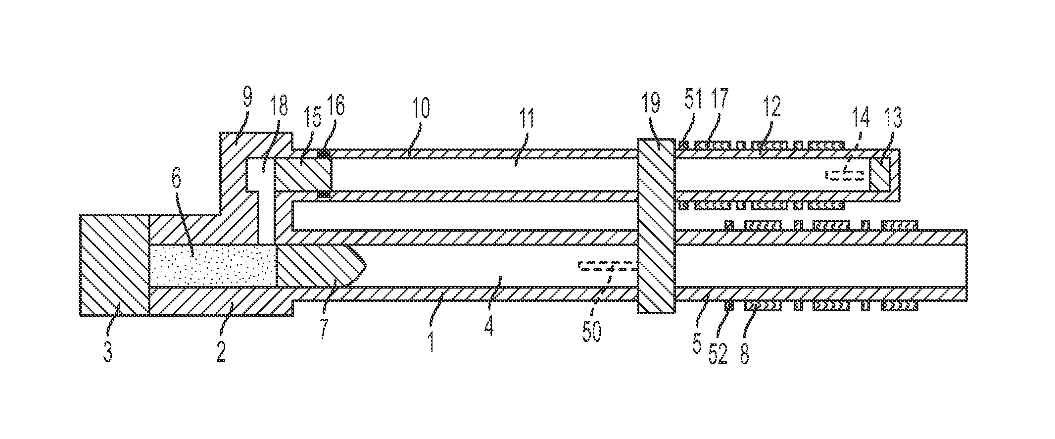
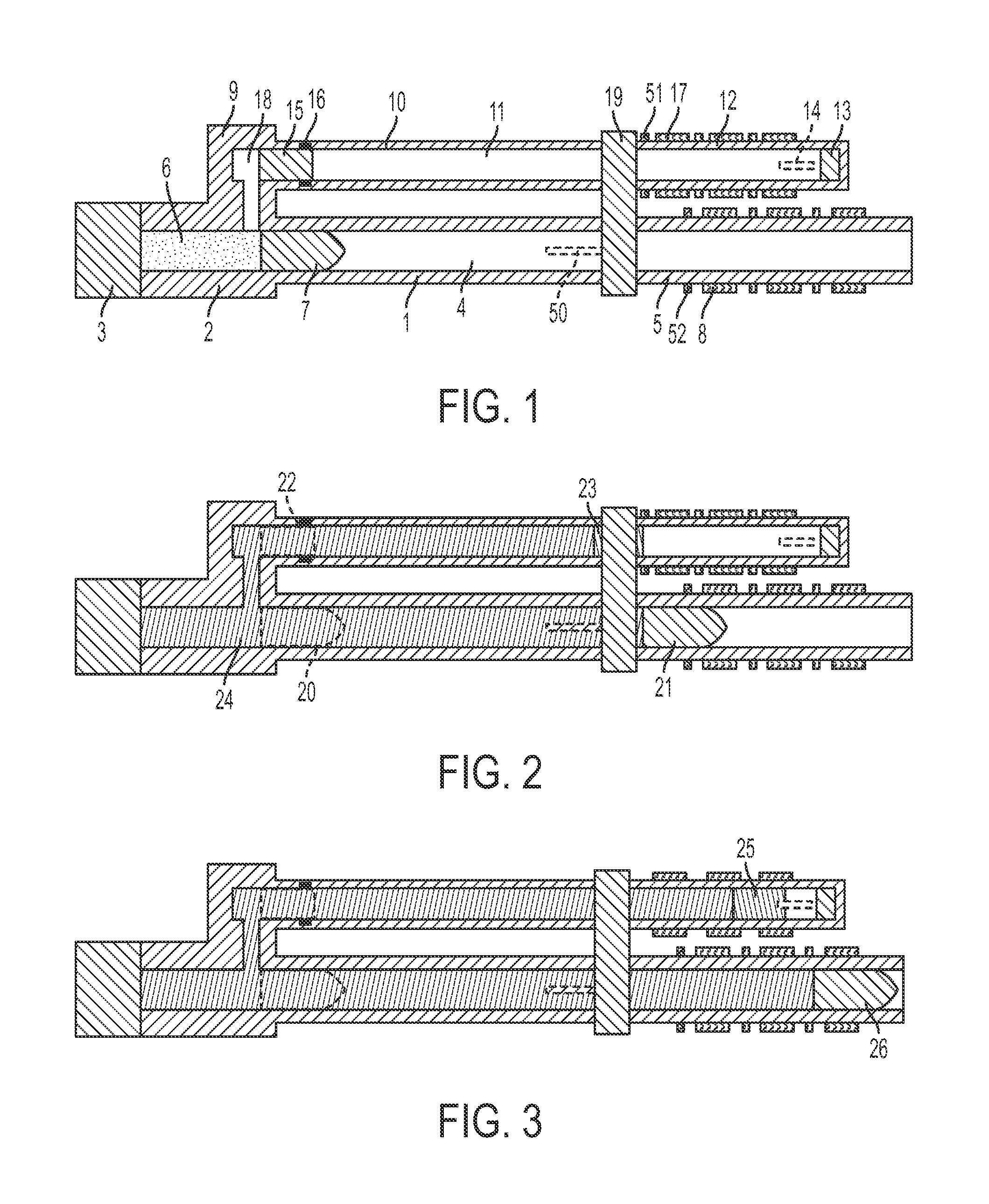
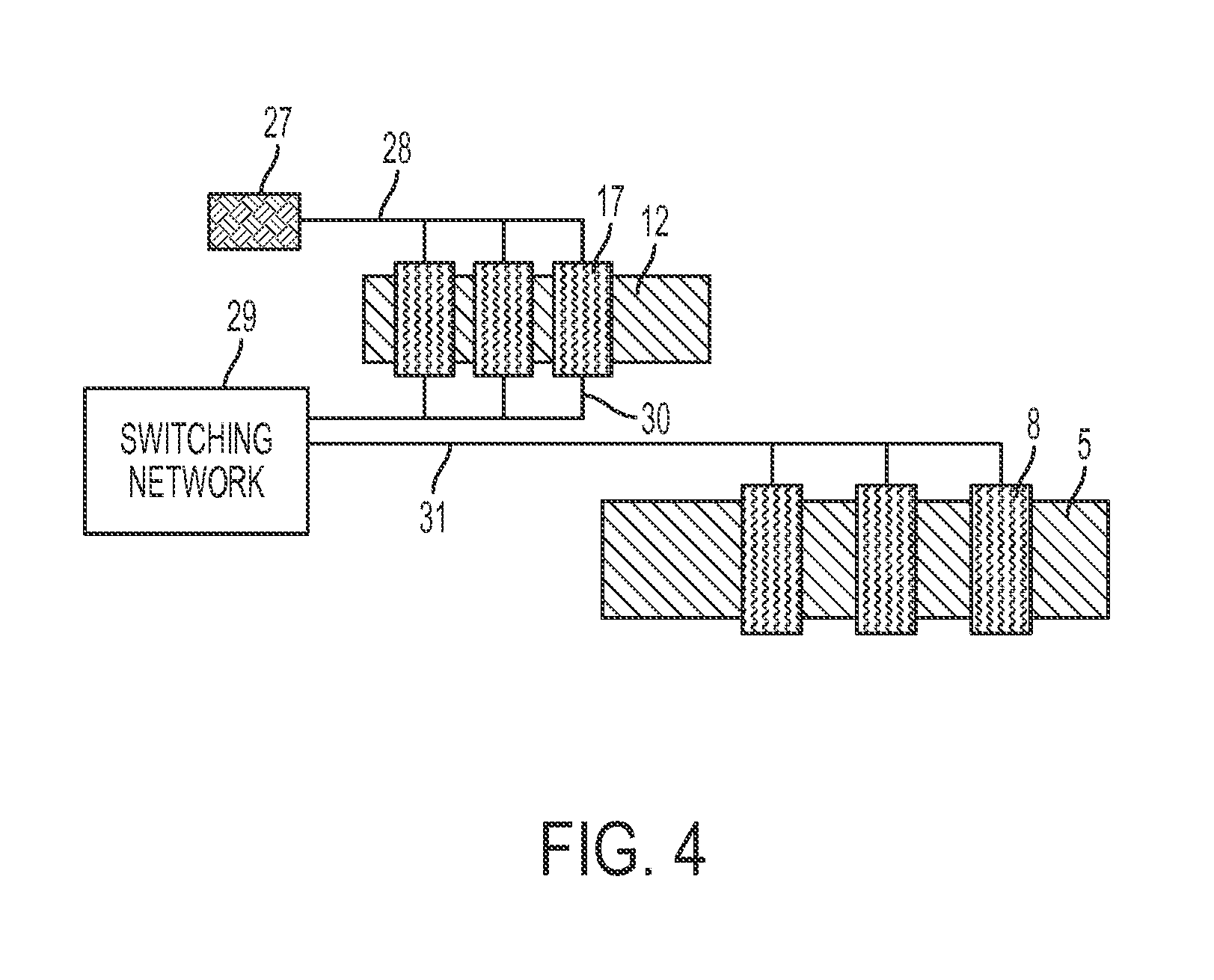
[0036]The basic components of a hybrid gun device for launching projectiles according to the invention are shown in FIGS. 1-4. The device includes a main barrel with breech, auxiliary barrel with breech, cartridge case of propellant, driver mass, projectile, deceleration and acceleration coils stages, an electrical switching network, and an external electrical source unit to supply a starting current for the coil stages along the auxiliary barrel.

[0037]As shown, the main gun portion of the system has a main barrel 1, a breech section 2 that houses the main barrel 1, a breechblock 3, a main barrel hollow core, or bore, 4 open at both ends, and a main barrel extension 5. The hollowed volume of the breech section 2 is filled with propellant 6. The main barrel breech 2 contains a projectile 7. Surrounding main barrel extension 5 are acceleration coil stages 8 and projectile position sensors 52. In addition, connected to the breech section 2 is an auxiliary breech section 9 to which auxi...


PUM


Abstract

A hybrid gun device composed of two barrels (1,10) that accept energy from combustion of standard propellant (6), one barrel (10) being operative to produce a high intensity electric current to add accelerating energy to a projectile (7) in the second barrel (1) and at least one coil (8) stage to convert energy between electrical and kinetic to cause the projectile (7) to be launched at hypervelocity.

Description

BACKGROUND OF THE INVENTION[0001]The present invention relates to conventional guns that use propellant energy in combination with electromagnetic energy in a coil system that acts to launch projectile mass in the hypervelocity regime. Electromagnetic coil gun projectile launch systems are already known in the art. An example thereof is disclosed in: “Design and Performance of Sandia's Contactless Coilgun for 50 mm Projectiles,” IEEE Transactions on Magnetics, Vol. 29, No 1, p. 680, January 1993, R. J. Kaye et al and the entirety of which is incorporated herein by reference. An integrated propellant and coil gun system is disclosed in: “Hypervelocity Projectile Launching System,” U.S. patent application Ser. No. 13 / 916, 176, 14 Jun. 2013, F. I. Grace et al, and the entirety of which is incorporated herein by reference.[0002]It is known that extremely high magnetic fields can be obtained using high current levels that are passed through helically wire-wound coils. When a moving ferro...

Claims


Application Information

Patent Timeline
Patent Type & Authority Applications(United States)
IPC IPC(8): F41B6/00H02K41/035H02K7/02H02K5/02H02K9/04F41A1/02H02K3/28
CPCF41B6/003F41A1/02H02K41/0356H02K7/025H02K5/02H02K9/04H02K3/28
Inventor GRACE, FRED IRVINYILBONG, KIMENIG, ERIC N.BENTZ, DANIELBARNARD, MICHAEL J.
Owner ENIG ASSOCS
Why Eureka
Try Eureka