
Vehicle braking force control device

a control device and steering wheel technology, applied in the direction of automatic initiation, brake systems, transportation and packaging, etc., can solve the problems of distortion, affecting the braking force, and the braking radius cannot be often designed to be small, so as to prevent and reduce the braking force of the steering wheel. , to achieve the effect of reducing the braking force of the steering wheel, preventing abnormal noise and swing of the vehicl

Active Publication Date: 2019-08-08
HITACHI ASTEMO LTD
View PDF0 Cites 5 Cited by
  • Summary
  • Abstract
  • Description
  • Claims
  • Application Information

AI Technical Summary

Benefits of technology

The invention prevents abnormal noise, reduces swing of a vehicle, and reduces the load on the steering wheel while also reducing stress accumulation during stationary steering. This results in lower loads on the tires, suspension, and steering device.

Problems solved by technology

However, the scrub radius cannot be often designed to be small due to various restrictions of a suspension device, the steering device, a driving force transmission device, and the like.
While the total drag amount of the tire at the time of stationary steering is larger as the scrub radius is large, here, the tire is not always dragged at the time of stationary steering, and a stress against the steering force is accumulated as distortion of each part of the vehicle, such as the tire, a brake device, the suspension device, or the steering device within a range not exceeding a frictional force between the tire and the ground.
These distortions are released when the vehicle starts traveling.
However, even in the stopped state, the distortion in a circumferential direction of the scrub radius can be released by loosening braking by the brake device to enable rotation of the steering wheel.

Method used


Image

  • Vehicle braking force control device
  • Vehicle braking force control device
  • Vehicle braking force control device

Examples


first embodiment

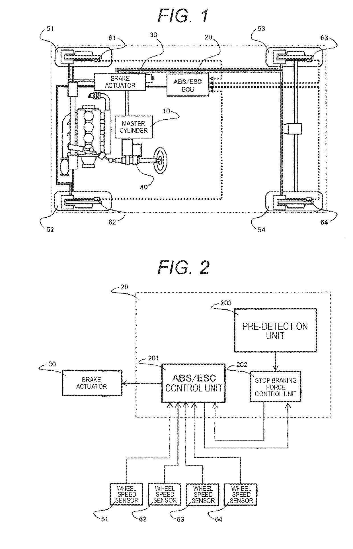
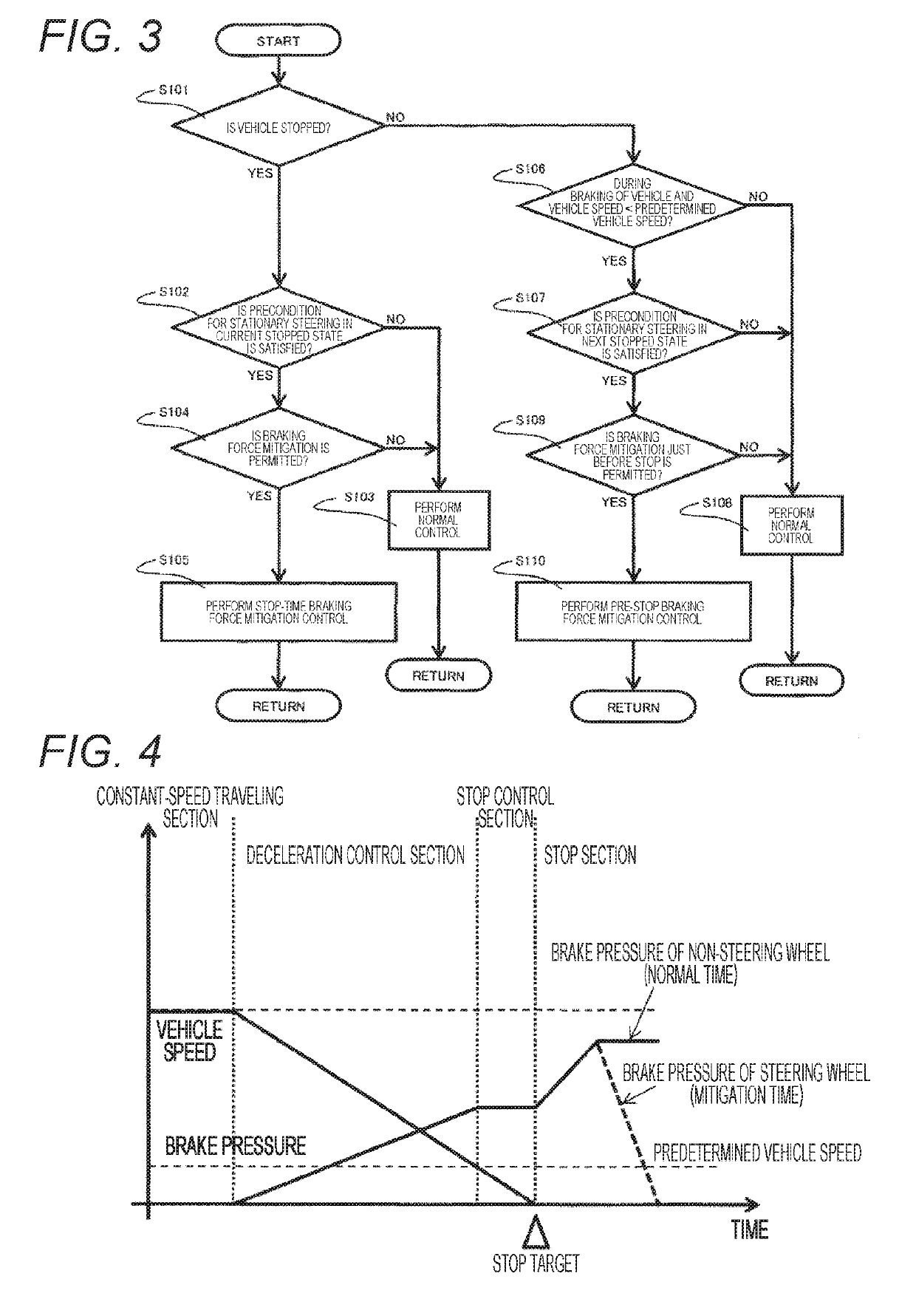
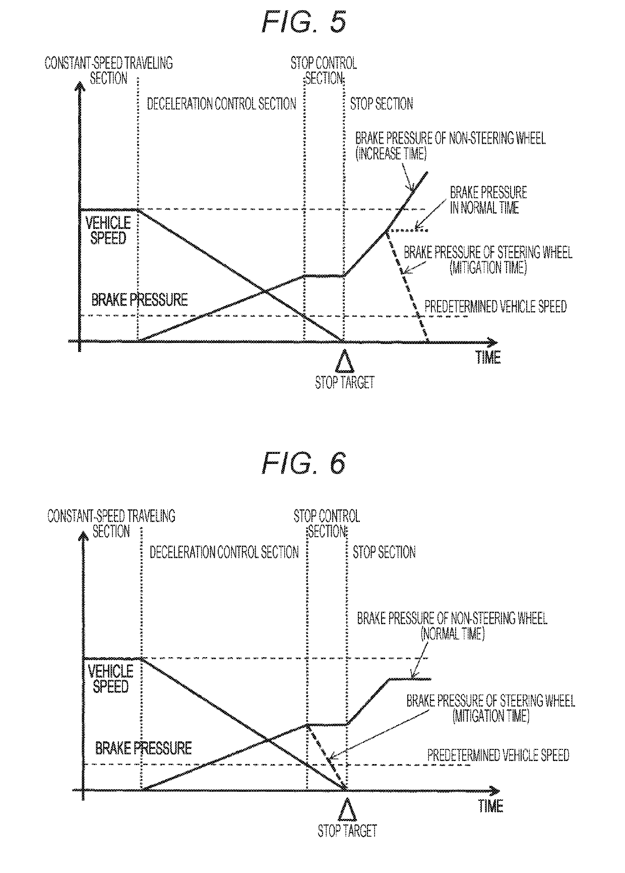
[0036]In the present embodiment, a case in which an occupant operates a vehicle on the basis of his / her own intention, and a case in which the occupant operates the vehicle while receiving some assistance from the vehicle side are assumed. A braking force control device according to the present embodiment executes control to decrease braking forces of steering wheels to be lower than the braking forces at the time of normal braking (hereinafter appropriately referred to as “braking force mitigation control”) in a case of detecting stationary steering in advance on the basis of a state of the vehicle and determining that there is no problem if such control is executed.

[0037]FIG. 1 is an overall configuration diagram illustrating an example of a braking force control system including a braking force control device according to a first embodiment of the present invention. In FIG. 1, a braking force control system includes a master cylinder 10, an ABS / ESC electronic control unit (ECU) 2...

second embodiment

[0069]In the present embodiment, a case in which an autopilot system, not an occupant, operates (including steers) a vehicle, and a case in which the occupant and the autopilot system share the operation of the vehicle are assumed. The autopilot system is a system that performs an automatic operation for the purpose of automatic parking, for example, and is a system that performs an automatic operation for the purpose of U turn. Such an autopilot system plans some traveling path before the start of an operation for the intended operation. A place having a possibility of stationary steering in the planned traveling path is planned in advance. Therefore, a braking force control device according to the present embodiment executes braking force mitigation control in a case of detecting the stationary steering in advance on the basis of an operation plan, and determining that there is no problem if decreasing braking forces of steering wheels 51 and 52.

[0070]FIG. 18 is a control block di...


PUM


Abstract

The present invention prevents occurrence of abnormal noise and swing of a vehicle in mitigating braking force of a steering wheel while reducing a steering load at the time of stationary steering to reduce a burden of a steering device and reducing stress accumulation due to stationary steering to reduce burdens of a tire, a suspension device and the steering device. The present invention includes a stop braking force control unit 202 that individually controls braking forces of steering wheels 51 and 52 and non-steering wheels 53 and 54 at the time of deceleration of the vehicle, and a pre-detection unit 203 that detects steering in a stopped state of the vehicle in advance, in which the stop braking force control unit executes, when the steering in a stopped state of the vehicle is detected in advance by the pre-detection unit, braking force mitigation control to decrease the braking forces of the steering wheels to be lower than the braking forces at the time of normal braking.

Description

TECHNICAL FIELD[0001]The present invention relates to a braking force control device that individually controls braking forces of steering wheels and non-steering wheels at the time of deceleration of a vehicle.BACKGROUND ART[0002]A driving operation to steer a stopped vehicle is called stationary steering and is a driving operation that enables turning with a minimum turning radius of the vehicle. Further, the turning radius during turning can be made constant by a stationary steering operation. The stationary steering operation has been conventionally carried out by many drivers because the stationary steering operation is sometimes necessary at the time of turning a vehicle in a narrow space and a traveling path of the vehicle can be simplified. Further, similarly in an autopilot system, the stationary steering operation is still an important driving operation for the necessity in a narrow space and the simplification of an operation algorithm.[0003]While in steering in the stopp...

Claims


Application Information

Patent Timeline
IPC IPC(8): B60T8/174B60T7/22B60T8/32
CPCB60T8/174B60T7/22B60T8/321B60T2250/04B60T2270/10B60T2270/30B60W30/06B60W10/18B60W10/20B60W30/18054B60W2520/12B60W2530/00B60W2510/109B60W2510/20B60W2520/26B60W2710/18B60W2710/20B62D6/001B62D15/0285B62D15/025B62D6/00B60T8/00B60T7/12B60T8/1755B60T2220/03
Inventor SAKAGUCHI, TOMOYASUYOSHIDA, YOSHIYUKISEIMIYA, MASASHIMATSUOKA, TAKASHI
Owner HITACHI ASTEMO LTD
Learn More