Explosion-protected fuel cell system and method for deactivating a fuel cell system

a fuel cell and explosion-protected technology, applied in the direction of fuel cells, motive system fuel cells, reactant parameter control, etc., can solve the problems of exceeding the lower explosive limit, at least severely restricting the exchange of gas between the housing interior and the environment, and particularly high hydrogen leakage rate, so as to minimize the risk of hydrogen explosion and structural simple

Active Publication Date: 2019-08-08
PROTON MOTOR FUEL CELL
View PDF4 Cites 4 Cited by
  • Summary
  • Abstract
  • Description
  • Claims
  • Application Information

AI Technical Summary

Benefits of technology

[0014]The object of the present invention therefore consists in providing a fuel cell system and methods of deactivating and reactivating a fuel cell system, in which the disadvantages of the prior art are eliminated or at least reduced. The system should be structurally simple and minimize the risk of a hydrogen explosion, especially when restarting the system after a longer downtime, but also during downtime itself. Preferably, it should be possible to completely or partly dispense with the use of expensive explosion-protected components.

Problems solved by technology

Although the housing is not necessarily gas-tight, the exchange of gas between the housing interior and the environment is at least severely restricted.
Hydrogen lines in fuel cell systems involve the additional problem that the hydrogen does not flow exclusively in welded pipelines, but that the hydrogen flow paths also have releasable connections such as threaded connections, for example, at the interfaces between tank module and supply line and between supply line and fuel cell module, as well as at all locations where sensors and actuators, such as valves or regulators, are integrated into the hydrogen lines.
At these locations, the hydrogen leakage rate is particularly high, especially when the hydrogen is at a higher pressure than the surrounding atmosphere.
Due to the compact design of fuel cell systems, the installation thereof in housings and confined spaces such as automobiles, thereby hindering the rapid escape of hydrogen, leakage of hydrogen from the lines can easily result in the lower explosive limit being exceeded.
Already the electrics system of the fuel cell system itself then may cause the gas mixture to ignite, thus triggering an explosion.
This primary explosion protection fails when the system is shut down or deactivated.
Many fuel cell systems are operated only for comparatively short periods of time while they are out of service for extended periods of time.
Fuel cell powered motor vehicles, for example, are usually out of operation for a much longer period than in operation.
Depending on the length of the lines and the pressure prevailing in the lines, the respective amount of hydrogen may be considerable and, together with the ambient air, may lead to the formation of explosive mixtures.
When the fuel cell system is activated or put into operation again, an explosion may be caused due to sparks that occur as a result of the activation of electrical components.
These measures are costly, result in a more complex structure and increased weight of the system, and moreover do not provide 100% explosion protection.
Explosions that are triggered by system-external ignition sources cannot be prevented in this way.

Method used


Image

  • Explosion-protected fuel cell system and method for deactivating a fuel cell system
  • Explosion-protected fuel cell system and method for deactivating a fuel cell system

Examples


Embodiment Construction

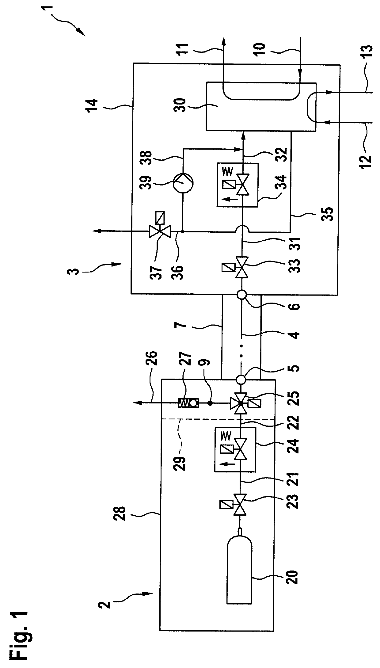
[0033]FIG. 1 schematically shows an embodiment of a fuel cell system 1 according to the invention. The fuel cell system 1 comprises a tank module 2 and a fuel cell module 3, wherein hydrogen can flow from the tank module 2 through a hydrogen supply line 4 into the fuel cell module 3.

[0034]In the embodiment illustrated, the tank module 2 comprises a high-pressure hydrogen reservoir (tank) 20, a main shut-off valve 23 for the tank 20 and a pressure reducer 24. Through a hydrogen line 21, hydrogen can flow from the tank 20 to the pressure reducer 24. Here, the hydrogen pressure is reduced to a pressure of preferably 0.5 MPa to 1.2 MPa and fed from there through a hydrogen line 22. The hydrogen flows through the 3 / 2-way valve 25 and enters the hydrogen supply line 4 which at the connection point 5 is connected to the hydrogen line 22. The length of the hydrogen supply line 4 is dependent on the distance between the tank module 2 and the fuel cell module 3, which is indicated by the dott...


PUM

PropertyMeasurementUnit
opening pressureaaaaaaaaaa
pressureaaaaaaaaaa
pressureaaaaaaaaaa

Abstract

The invention relates to a fuel cell system having lines for feeding hydrogen from a high-pressure hydrogen reservoir into a fuel cell assembly. The lines have a high-pressure region, a medium-pressure region, and a fuel cell operating-pressure region. The lines of the medium-pressure region are pressure-relieved upon deactivation of the fuel cell system in order to avoid hydrogen diffusing out during standstill periods of the fuel cell system, and to thus avoid the formation of explosive hydrogen/air mixtures. The invention also relates to a tank module, which is configured for pressure relieving, to a method of deactivating and re-activating the fuel cell system, to the use of a 3/2-way valve for pressure-relieving the medium-pressure region of the hydrogen lines of a fuel cell system, and to a motor vehicle having a fuel cell system or tank module.

Description

BACKGROUND OF THE INVENTIONField of the Invention[0001]The invention relates to a fuel cell system in which the formation of explosive gas mixtures is avoided during downtimes of the fuel cell system, and to a method of deactivating or shutting down a fuel cell system, which avoids the formation of explosive gas mixtures after deactivation, so that safe reactivation of the fuel cell system is possible.Description of the Related Art[0002]Fuel cells generate electrical energy from hydrogen and oxygen. Oxygen is usually supplied in the form of air, and hydrogen is supplied from a reservoir or generated locally, for example from methanol. The most common variant both for mobile and for stationary fuel cell systems is the hydrogen supply from high-pressure tanks. In the high-pressure tanks, hydrogen is stored under a pressure of up to 80 MPa (800 bar). One or more high-pressure tanks form a tank module. At the outlet of the tank module, the pressure is reduced by means of a pressure redu...

Claims


Application Information

Patent Timeline
Patent Type & Authority Applications(United States)
IPC IPC(8): H01M8/04955H01M8/04223H01M8/04089H01M8/04746H01M8/04082
CPCH01M8/04955H01M8/04231H01M8/04089H01M8/04753H01M8/04201H01M2250/20H01M2008/1095Y02E60/32Y02E60/50H01M8/04228
Inventor LANZINGER, ACHIM
Owner PROTON MOTOR FUEL CELL
Why Eureka
Try Eureka