Microelectronic treatment system having treatment spray with controllable beam size

a microelectronic treatment and control beam technology, applied in the direction of cleaning process and apparatus, cleaning of flexible articles, cleaning using liquids, etc., can solve the problems of difficult to provide, cryogenic treatment, and less practical scanning nozzle in cryogenic tools

Active Publication Date: 2019-08-22
TEL EPION
View PDF0 Cites 5 Cited by
  • Summary
  • Abstract
  • Description
  • Claims
  • Application Information

AI Technical Summary

Benefits of technology

[0007]This invention relates to systems and methods that produce a treatment beam with a controllable beam size. In illustrative embodiments, control of process chamber pressure adjusts the beam size of a treatment beam used to treat the surface of one or more microelectronic substrates. Using pressure to control beam size is advantageous, as physical changes to the processing environment are not required to tune the treatment beam within a wide range of size options for a given tool configuration. Bea...

Problems solved by technology

However, a scanning nozzle is less practical in a cryogenic tool, because a cryogenic rotary coupling has been difficult to provide in a practical manner.
A significant challenge is to use cryogenic treatments to remove smaller particles, e.g., contaminant particles having a size u...

Method used


Image

  • Microelectronic treatment system having treatment spray with controllable beam size
  • Microelectronic treatment system having treatment spray with controllable beam size
  • Microelectronic treatment system having treatment spray with controllable beam size

Examples


example 1

[0083]Referring to FIG. 5, tests (Tests 1 and 2) were conducted to demonstrate small particle cleaning of a 300 mm, bare silicon wafer 200 having a surface 201 contaminated with 30 nm silica particles and then exposed to cryogenic aerosol treatment beams at two different chamber pressures, respectively. A relatively more concentrated treatment beam at relative higher vacuum chamber pressure of 19 Torr was used for one test. This was compared to a larger, more diffuse treatment beam at lower chamber pressure of 4 Torr under otherwise the same conditions for a second test.

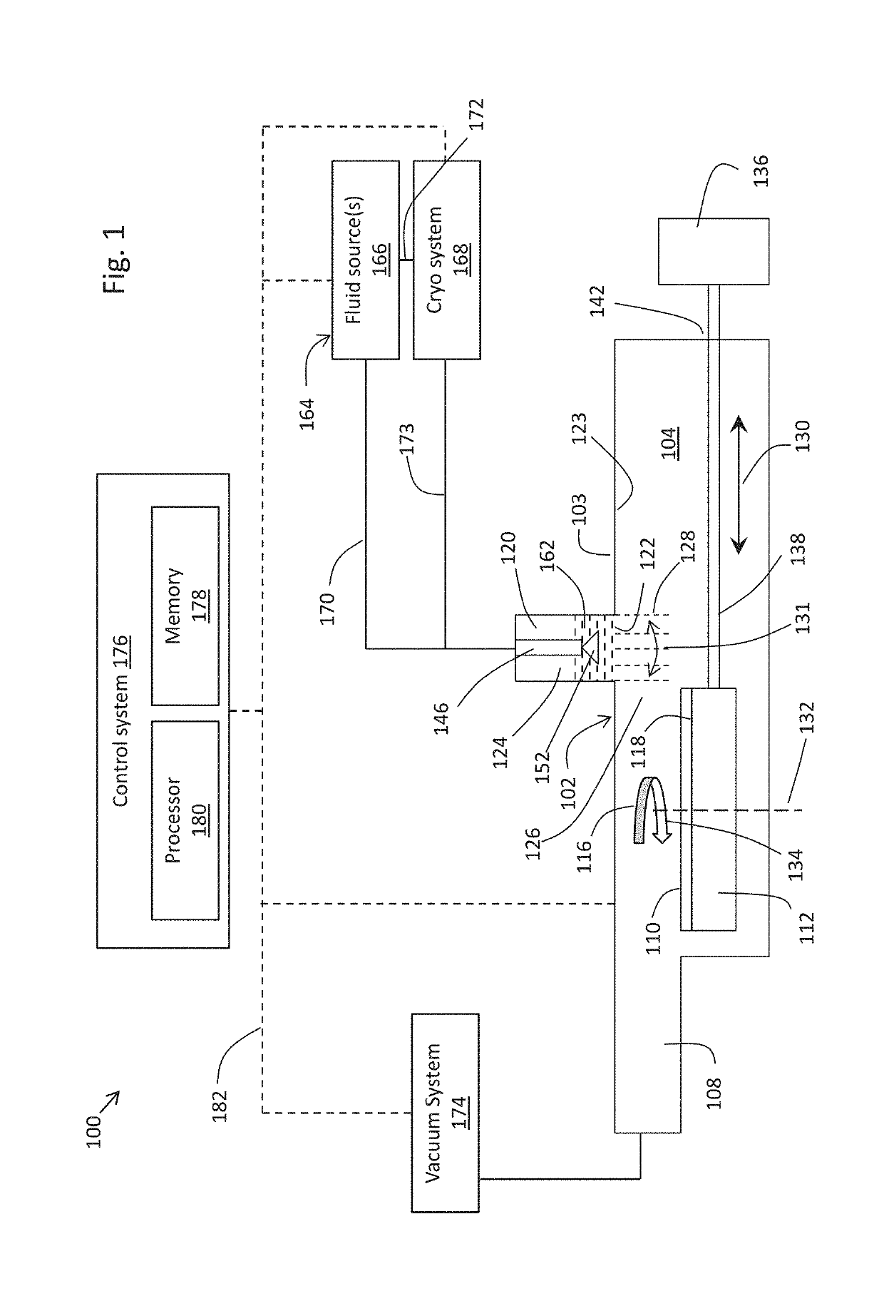
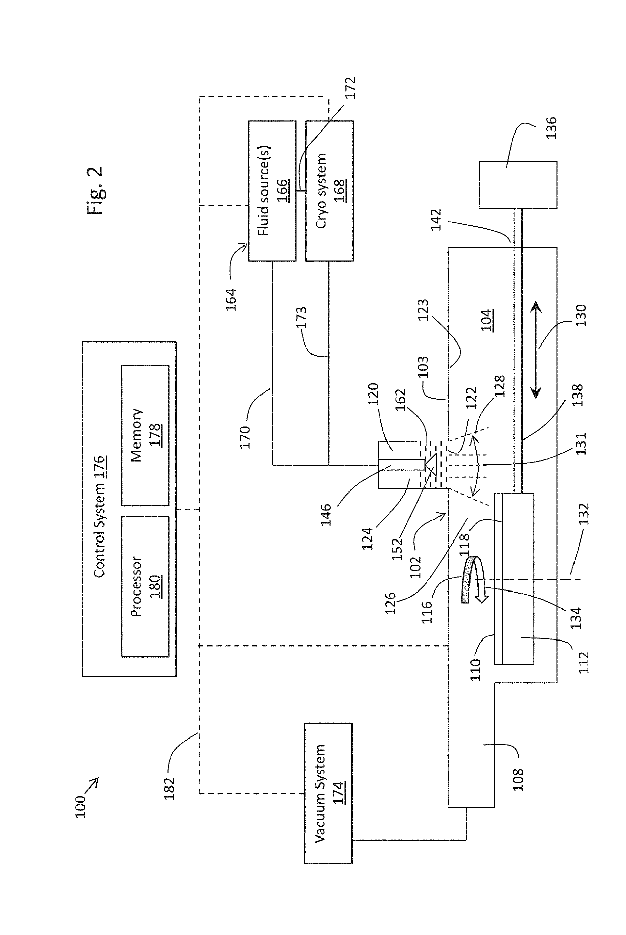
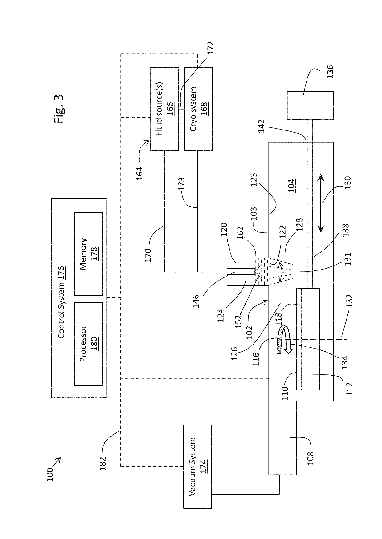
[0084]To prepare the wafer for testing, 30 nm silica particles were wet deposited onto the bare silicon wafer 200, aged for 3 hours, and then placed into a vacuum chamber in a cryogenic treatment tool according to FIG. 1 and FIG. 4. The tool was configured to have, the capability to control the chamber pressure. A nozzle was mounted in a cylindrical auxiliary chamber such that the nozzle orifice was 50 mm from the su...

example 2

[0092]Tests were conducted to evaluate how flow rate and chamber pressure impact the shape and size of fluid treatment beams used to clean particles from wafer surfaces. The tests were conducted using a 300 mm, bare silicon wafer having a surface contaminated with 30 nm silica particles. The contaminated wafer was exposed to fluid treatment beams in four different tests (Tests 3, 4, 5 and 6) using the conditions reported in Table 2-1.

[0093]To prepare each test wafer for testing, 30 nm silica particles were wet deposited onto the bare silicon wafer 200, aged for 1 hour, and then placed into a vacuum chamber in a cryogenic treatment tool according to FIG. 1 and FIG. 4. The tool was configured to have, the capability to control the chamber pressure. A nozzle was mounted in a cylindrical auxiliary chamber such that the nozzle orifice was 50 mm from the substrate. The nozzle orifice was 0.0925 inches (2.35 mm) in diameter. The nozzle also was recessed 27 mm within the cylindrical auxilia...

example 3

[0100]Tests were conducted to evaluate how flow rate, nozzle orifice size, and gap distance (shown as gap distance 126 in FIG. 4) impact the shape and size of fluid treatment beams used to clean particles from wafer surfaces. The tests were conducted using a 300 mm, bare silicon wafer having a surface contaminated with 100 nm silica particles. The contaminated wafer was exposed to fluid treatment beams in three different tests (Tests 7, 8 and 9) using the conditions reported in Table 3-1. For all three tests, pressurized and cooled argon was supplied to the nozzle −173 C (100 K) at the pre-expansion pressures shown in Table 3-1. The pressure and temperature were selected to help ensure that the pressurized and cooled argon supplied to the nozzle remained as a gas in the supply line to avoid liquid content. For all three tests, the nozzle was positioned with its outlet orifice outside the auxiliary chamber and projecting into the process chamber so that the nozzle outlet was not rece...


PUM


Abstract

This invention relates to systems and methods that produce a treatment beam with a controllable beam size. This is accomplished by providing an auxiliary chamber in open fluid communication with the main process chamber. A nozzle is mounted in a recessed manner in the auxiliary chamber. The nozzle dispenses a treatment spray into the auxiliary chamber. The auxiliary chamber shapes and dispenses the treatment material as a treatment beam into the process chamber. In illustrative embodiments, control of process chamber pressure adjusts the beam size of a treatment beam used to treat the surface of one or more microelectronic substrates.

Description

PRIORITY[0001]This application claims priority to U.S. Provisional Patent Application No. 62 / 632,131, filed Feb. 19, 2018, titled “Microelectronic Treatment System Having Treatment Spray with Controllable Beam Size,” the entire disclosure of which is incorporated herein by reference for all purposes.FIELD OF USE[0002]This disclosure relates to an apparatus and method for treating the surface of one or more microelectronic substrates, e.g., cleaning residue, debris, and other materials from a surface of a microelectronic substrate. More specifically, the disclosure relates to such an apparatus in which pressure is controlled to adjust the beam size of a treatment stream used to treat the surface of one or more microelectronic substrates.BACKGROUND OF THE INVENTION[0003]Advances in microelectronic technology cause integrated circuits (ICs) to be formed on substrates, such as semiconductor substrates, with ever increasing density of active components. The formation of ICs is carried ou...

Claims


Application Information

Patent Timeline
IPC IPC(8): B08B11/00B08B5/02B08B5/04B08B3/02
CPCB08B11/00B08B5/02B08B5/04B08B3/02H01L21/67051H01L21/6776H01L21/68764
Inventor MBANASO, CHIMAOBI W.
Owner TEL EPION
Why Eureka
Try Eureka