Apparatus for callus removal

a technology for callus and applicator, which is applied in the field of skin treatment devices, can solve the problems of difficult control of devices having a disk-shaped abrasive element, difficult control of devices, and difficulty for users to precisely maintain device position, so as to improve the hygienic properties of devices, reduce malodorous scent, and reduce the effect of malodorous scen

Pending Publication Date: 2019-08-29
KONINKLJIJKE PHILIPS NV
View PDF1 Cites 0 Cited by
  • Summary
  • Abstract
  • Description
  • Claims
  • Application Information

AI Technical Summary

Benefits of technology

[0022]According to a further preferred embodiment, said protective rim comprises a circumferential inner edge, wherein said circumferential inner edge partially surrounds said skin treatment element and protrudes above or is flush with said axial abrasive treatment surface such that particles thrown radially outward along said axial abrasive skin treatment surface are collected by said inner edge and directed into a particle collecting space. Generally, the inventors observed a malodorous scent occurring frequently when callus is removed by a grinding action. The inventors found that such malodorous scent can be significantly reduced if the particles produced by the grinding removal of the callus are collected in a collecting space rather than allowing these ground-off particles to be thrown away from the device. According to this embodiment, the protective rim provides an additional function in that the protective rim further acts as a catch ring which catches the ground-off particles. This catching function is enabled by the particles being spun off the skin treatment element by centrifugal force in a radial/tangential direction and then hitting the circumferential inner edge such that the particles are collected at said inner edge or the inner edge directs the particles to the particle collecting space. It is understood that the circumferential inner edge may only protrude above the axial abrasive treatment surface over a small distance being in a range of a few millimeters only or even below 1 millimeter. Generally, the small particles thrown radially off the axial abrasive treatment surface will usually be collected together even if such a small protruding distance of the inner edge is provided. The inner edge may be formed such that the particles are directed by the inner edge directly into the collecting space, but the transport of the particles into the collecting space may be supported by other means like e.g. an airflow produced by the axial abrasive treatment surface or a separate fan or blower component. It was found by the inventors that by collecting the particles the malodorous scent can be reduced significantly since these particles were identified to produce the malodorous scent. Further, the embodiment comprising the circumferential inner edge improves the hygienic properties of the device in that no particles, dust and the like are thrown out of the device or the release of such particles and dust is at least significantly reduced.
[0023]The embodiment can be further improved by a conveying device for conveying particles collected in said collecting space to a collecting box. Generally, the particles caught by the inner edge may be collected in the collecting space only, which usually is placed close to or adjacent to the inner edge. However, this may require frequent cleaning of the collecting space to remove the particles accumulated therein. According to this preferred embodiment the particles are conveyed out of the collecting space into a collecting box which may have sufficient capacity to avoid the need for frequent cleaning.
[0024]While such a conveying device may be a separate unit with a separate drive mechanism, it is in particular preferred that said conveying device is embodied as a fan driven by said drive mechanism. According to this improvement the conveying device is driven by the drive mechanism driving the skin treatment element and thus the need for a second, independent driving means is avoided. The fan preferably provides a radial-axial co

Problems solved by technology

Various problems are related to such callus removal devices.
The configuration having a roller with a circumferential abrasive surface was found to produce significant local abrasion but is difficult to handle and control in such a way that a constant abrasion over a larger area of the skin is achieved.
Devices having a disk-shaped abrasive element are difficult to control, since in conditions where the disk is in contact with the skin at a slightly angular orientation, i.e. with the rotational axis not being exactly perpend

Method used


Image

  • Apparatus for callus removal
  • Apparatus for callus removal
  • Apparatus for callus removal

Examples


first embodiment

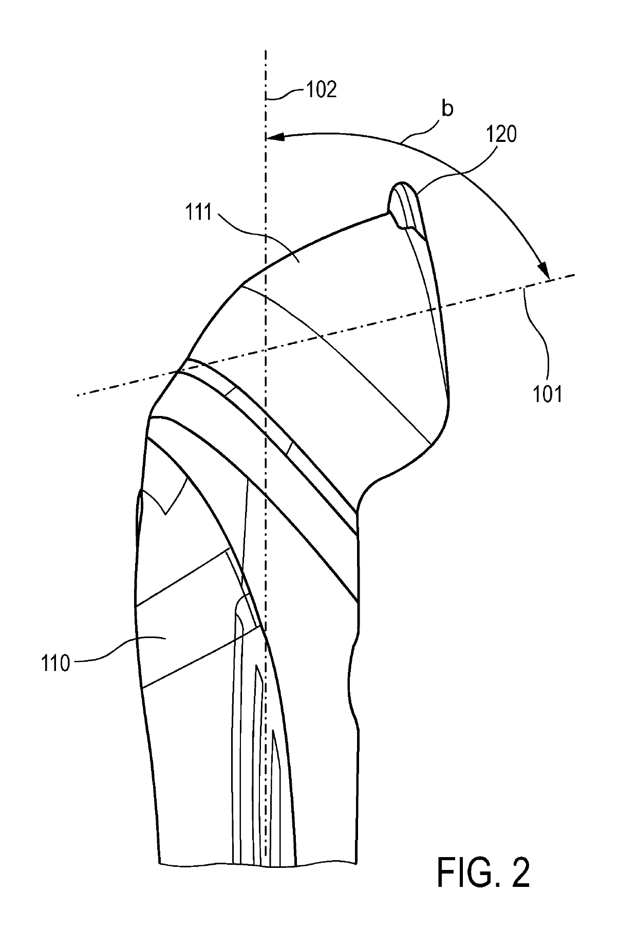
[0059]FIG. 2 shows a skin treatment device according to the invention. The skin treatment device generally comprises a housing incorporating a handle section 110 and a treatment head section 111. The handle section 110 may incorporate an electrical motor, a rechargeable battery coupled to said motor for energy supply, a socket for recharging said battery and a user interface adapted to control the motor. The user interface may comprise an on-off switch and may further comprise control means for adjusting parameters of the electrical motor like rotational speed, direction of rotation, unidirectional or oscillatory motion and the like. Further, a display may be incorporated displaying parameters like rotational speed, type of motion or battery level.

[0060]As can be seen in FIG. 2, the treatment head 111 comprises a disk-shaped treatment element 120 at one end. The disk-shaped treatment element is generated for rotational movement about a rotational axis 101. As can be seen, the rotati...

second embodiment

[0070]FIG. 9c shows a different protective rim 330b mounted to the treatment head. As can be seen, this protective rim 330b comprises a first and a second rim section 331b, 332b being arranged opposite to each other and thus providing two non-encased angular regions 333b, 334b of the skin treatment element. The first non-encased angular region 334b is identical to the non-encased angular region of 135° described with reference to the first and the The second non-encased angular region 333b is opposed to this first angular region and extends through approximately the same angle as the first angular region.

[0071]FIGS. 10a,b show a fourth embodiment of the invention. The skin treatment device according to this fourth embodiment comprises a protective rim 430 which is designed so as to be mainly identical to the protective rim 130 of the first embodiment shown in FIGS. 2-6, some design change being made at the angular end portions 430a,b of the protective rim which are designed to have...

sixth embodiment

[0075]FIG. 12a shows a detailed view of a treatment head of a sixth embodiment having a specific design of a protective rim extending over a partial angular range around a form-locking member 640 which is adapted for attachment of the skin treatment element. It is understood that this specific design may be incorporated in all five embodiments explained hereinbefore. The embodiment shown in FIG. 12a comprises a protective rim 630 which is composed of a plurality of rim segments 630a-k. In the embodiment shown in FIG. 12a, a total number of 11 rim segments form a continuous protective rim extending through an angular range of approximately 225° and leaving an open gap of approximately 135°. The two rim segments 630a, k adjacent to said gap and positioned at the respective ends of the protective rim are somewhat longer than the other rim segments 630b-j.

[0076]Each rim segment comprises an axially extending pin with a non-circular cross-section which is inserted into a corresponding o...


PUM


Abstract

The invention relates to a skin treatment device for removing callus from the skin by an abrasive treatment, comprising a housing with a handle section (110), a skin treatment element (120) rotatable around a rotational axis (101) and a protective rim (130). Said protective rim circumferentially encases said skin treatment element partially over an angular range of more than 120° and less than 330° about said rotational axis such that a circumferential abrasive treatment surface protrudes from the protective rim in an area extending over an angular range of 30° to 240°.

Description

FIELD OF THE INVENTION[0001]The invention relates to a skin treatment device for removing callus from the skin by an abrasive treatment.BACKGROUND OF THE INVENTION[0002]Callus removal from the skin can generally be done manually using appropriate hand tools like files, pumice stones and creams. A more effective and time-saving way to remove callus from the skin is the use of electrically driven devices having an abrasive surface which is driven into motion relative to the skin. The callus can be ground off by such devices. Predominantly, such devices are configured such that a roller with an abrasive circumferential surface is driven to rotate about an axis and is mounted to a handle extending in a direction perpendicular to the axis. The roller can be guided across the skin with the rotating axis of the roller being parallel to the skin surface. In this way, the circumferential surface of the roller abrades and grinds off the callus.[0003]According to another setup of such a callus...

Claims


Application Information

Patent Timeline
IPC IPC(8): A61B17/32A46B13/00A46B13/02
CPCA61B17/32A46B13/008A46B13/02A61B2017/00473A46B2200/1006A61B2017/00761A61B2017/320012A61B2090/08021A61B2217/005A61B2017/00734A61B2017/00398A61B17/54A61B2017/320004
Inventor VAN DER SCHEER, ROBBERT FREERK JOHANGLAZENBURG, JOOST TOMASKOENEN, MAURITSWOLF, HAROLDBEUGELS, JOHANNESSHRIVASTAVA, ADARSH
Owner KONINKLJIJKE PHILIPS NV
Why Eureka
Try Eureka