Passive pitch angle adjustment apparatus

a technology of pitch adjustment and apparatus, which is applied in the direction of rotors, aircrafts, vehicles, etc., can solve the problems of unbalanced lift at the different rotor blades, vibratory stresses on the rotor blades, and requires complex, heavy, and cost-intensive pitch adjustment devices, so as to reduce the bending moments, reduce the cost of purchase and maintenance, and increase the efficiency of the rotor system

Active Publication Date: 2019-08-29
AIRBUS HELICOPTERS DEUT GMBH
View PDF0 Cites 9 Cited by
  • Summary
  • Abstract
  • Description
  • Claims
  • Application Information

AI Technical Summary

Benefits of technology

[0015]Based on the limitations and drawbacks of the prior art, an objective is to provide a passive pitch angle adjustment apparatus for a rotor having rotor blades. The passive pitch angle adjustment apparatus should use the existing aerodynamic forces of a rotating rotor with at least two rotor blades as input signal and as actuation forces to provide torsion moments on the rotor blade axis of the respective rotor blade and thereby an adjustment of the pitch angle of the respective rotor blade. The passive pitch angle adjustment apparatus should be relatively simple, lightweight, and have low purchase and maintenance costs while not requiring any active control means. The passive pitch angle adjustment apparatus should provide an increased efficiency of the rotor system in case of lateral air flow with reduced bending moments and vibration on the rotor head and rotor axis due to balanced lift forces.

Problems solved by technology

In non-axial inflow fields, some rotor blades are rotating against the lateral air flow while others are rotating with the lateral air flow, which leads to unbalanced lift at the different rotor blades, depending on their current position.
Unbalanced lift often leads to vibratory stresses on the rotor blades.
In actively controlled rotor assemblies, each associated rotor blade is articulated and controlled individually over its azimuth angle of rotation, which often requires complex, heavy, and cost intensive pitch adjustment devices that require active control means with external energy supplies to adjust the pitch angle of each rotor blade individually.
However, the cyclic and collective pitch adjustment devices are generally embodied with a comparatively great complexity and weight and require the implementation of cost-intensive, complex controlling mechanisms and surveillance means.
These elements need to be moved by additional actuators, which therefore create extra costs including recurring costs for maintenance.
However, due to a comparatively high number of constituent components, this variable pitch propeller has a pitch adjustment mechanism that is comparatively complex, heavy, and cost intensive.
Furthermore, this pitch adjustment mechanism is only suitable for a high stiffness rotor assembly, where a respective frequency of the first lead-lag eigenmode, i. e. bending of the rotor blades within the plane of rotation relative to an associated rotor hub, is larger than two times a given rotational frequency of the rotor assembly.
This is, however, not applicable to large rotor assemblies, as the provided high stiffness leads to high bending loads, which would be prohibitively large.
Furthermore, even for comparatively small rotor assemblies with a diameter of less than 2 m, occurring loads may become prohibitively large if the rotor assemblies are used in conditions with comparably large lateral flow speeds, i.e. with an angle between flow direction and rotation axis of more than 15°.
Therefore, the effects of sidewinds or a sideward flight cannot be recovered by this stabilizing system.

Method used


Image

  • Passive pitch angle adjustment apparatus
  • Passive pitch angle adjustment apparatus
  • Passive pitch angle adjustment apparatus

Examples


Embodiment Construction

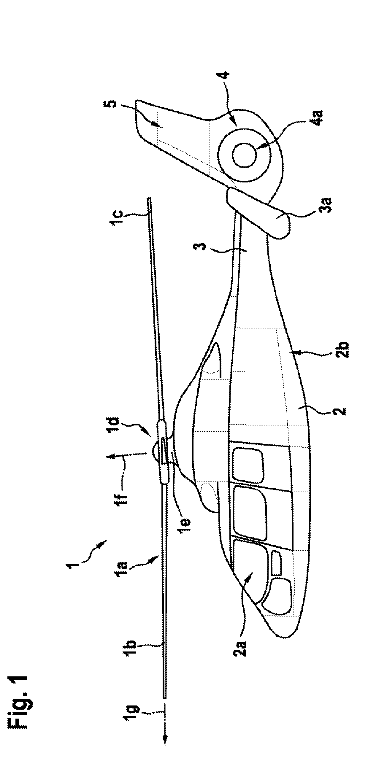
[0039]Exemplary embodiments may be included with any rotor or propeller having at least two rotor blades. For example, embodiments may be included in a rotor or a propeller of a transportation vehicle, if desired. FIG. 1 shows an example of a transportation vehicle. A transportation vehicle may be an airplane, a quadcopter, a helicopter, or any other rotary wing transportation vehicle. As shown in FIG. 1, the transportation vehicle may be a rotorcraft 1 that is exemplarily illustrated as a helicopter. Thus, for purposes of simplicity and clarity, the rotorcraft 1 is hereinafter referred to as the “helicopter”1.

[0040]Illustratively, helicopter 1 may have a fuselage 2 that forms an airframe of the helicopter 1. The fuselage 2 is connected to a suitable landing gear and exemplarily forms a cabin 2a and a rear fuselage 2b. The rear fuselage 2b is connected to a tail boom 3.

[0041]Illustratively, helicopter 1 may have at least one multi-blade rotor 1a for providing lift and forward or bac...


PUM


Abstract

A rotor or propeller may have rotor blades and a passive pitch angle adjustment apparatus. The passive pitch angle adjustment apparatus may include levers, rods, and central rod. Levers may be connected to rotor blades and rotate them around a respective pitch axis. Rods may be connected to levers and mechanically link levers with each other via central point that is located outside rotor plane. Central rod may connect central point with base point that is located in a longitudinal direction of rotor axis. The passive pitch angle adjustment apparatus may enable a cyclic pitch adjustment of the rotor blades and block a collective pitch adjustment of the rotor blades.

Description

CROSS-REFERENCE TO RELATED APPLICATIONS[0001]This application claims priority to European patent application No. EP 18400006.5 filed on Feb. 28, 2018, the disclosure of which is incorporated in its entirety by reference herein.BACKGROUND OF THE INVENTION(1) Field Of The Invention[0002]The invention is related to rotors and propellers, and, more particularly, to a passive pitch angle adjustment apparatus for controlling the pitch angle of the rotor blades of a rotor or propeller.(2) Description Of Related Art[0003]Rotors are usually provided for producing thrust in a predetermined direction during operation. The thrust produced by the rotor blades of a rotor can be controlled in two different ways: either by controlling the rotation speed of the rotor blades around the rotor axis, or by controlling an aerodynamic lift coefficient of the rotor blades. The aerodynamic lift coefficient is usually controlled by adjusting an underlying pitch angle of the rotor blades.[0004]Pitch angle adj...

Claims


Application Information

Patent Timeline
Patent Type & Authority Applications(United States)
IPC IPC(8): B64C27/72B64C27/39B64C27/04
CPCB64C27/72B64C2027/7205B64C27/04B64C27/39B64C27/59B64C27/51B64C27/58
Inventor SCHMIEDEL, PATRIKLEITNER, HARALDKRAUS, JULIANDANNEMANN, LUDWIGKIESEWETTER, UWE
Owner AIRBUS HELICOPTERS DEUT GMBH
Why Eureka
Try Eureka