Information recording device and data erasing method

a technology of information recording and data erasing, which is applied in the direction of overwriting/replacing recorded data, recording signal processing, instruments, etc., can solve the problems of corrupted data and made non-reproducible, data is erased, and the quality of a servo signal in the servo control may be degraded, so as to prevent the reduction of the quality of a servo signal and ensure the stability of the servo control. ,

Active Publication Date: 2019-09-12
PANASONIC INTELLECTUAL PROPERTY MANAGEMENT CO LTD
View PDF5 Cites 0 Cited by
  • Summary
  • Abstract
  • Description
  • Claims
  • Application Information

AI Technical Summary

Benefits of technology

[0005]If an amount of the data to be corrupted is increased in order to increase reliability of the erasing, then an amount of such newly formed recording marks is increased. Therefore, a ratio of the recording mark area to the space area is increased, and accordingly, there is a possibility that quality of a servo signal in the servo control may be degraded and it may become impossible to perform the stable servo control.
[0006]The present disclosure provides an information recording device capable of realizing the data erasing of the write-once optical disc with high reliability without affecting stability of the servo.
[0009]The information recording device according to the disclosure makes it possible to prevent reduction of the quality of a servo signal and thereby secure stability of a servo control. Furthermore, since the information recording device according to the disclosure corrupts data that is necessary for synchronization in data reproduction, it can disable data reproduction reliably and erase data reliably.

Problems solved by technology

In this way, the data is corrupted and made non-reproducible, and the data is erased.
Therefore, a ratio of the recording mark area to the space area is increased, and accordingly, there is a possibility that quality of a servo signal in the servo control may be degraded and it may become impossible to perform the stable servo control.
Moreover, the data erasing method corrupts data of an area in which information necessary for synchronization at a time of reproducing the data is recorded, the area being included in an erased area on the optical disc, the erased area being determined by the erase start position and the size of the data to be erased, by overwriting the data of the area by an erasing pattern, and thus erasing data of the erased area.
Furthermore, since the information recording device according to the disclosure corrupts data that is necessary for synchronization in data reproduction, it can disable data reproduction reliably and erase data reliably.

Method used


Image

  • Information recording device and data erasing method
  • Information recording device and data erasing method
  • Information recording device and data erasing method

Examples


first exemplary embodiment

1. Configuration

[0031]1.1 Configuration of Information Recording / Reproducing Device

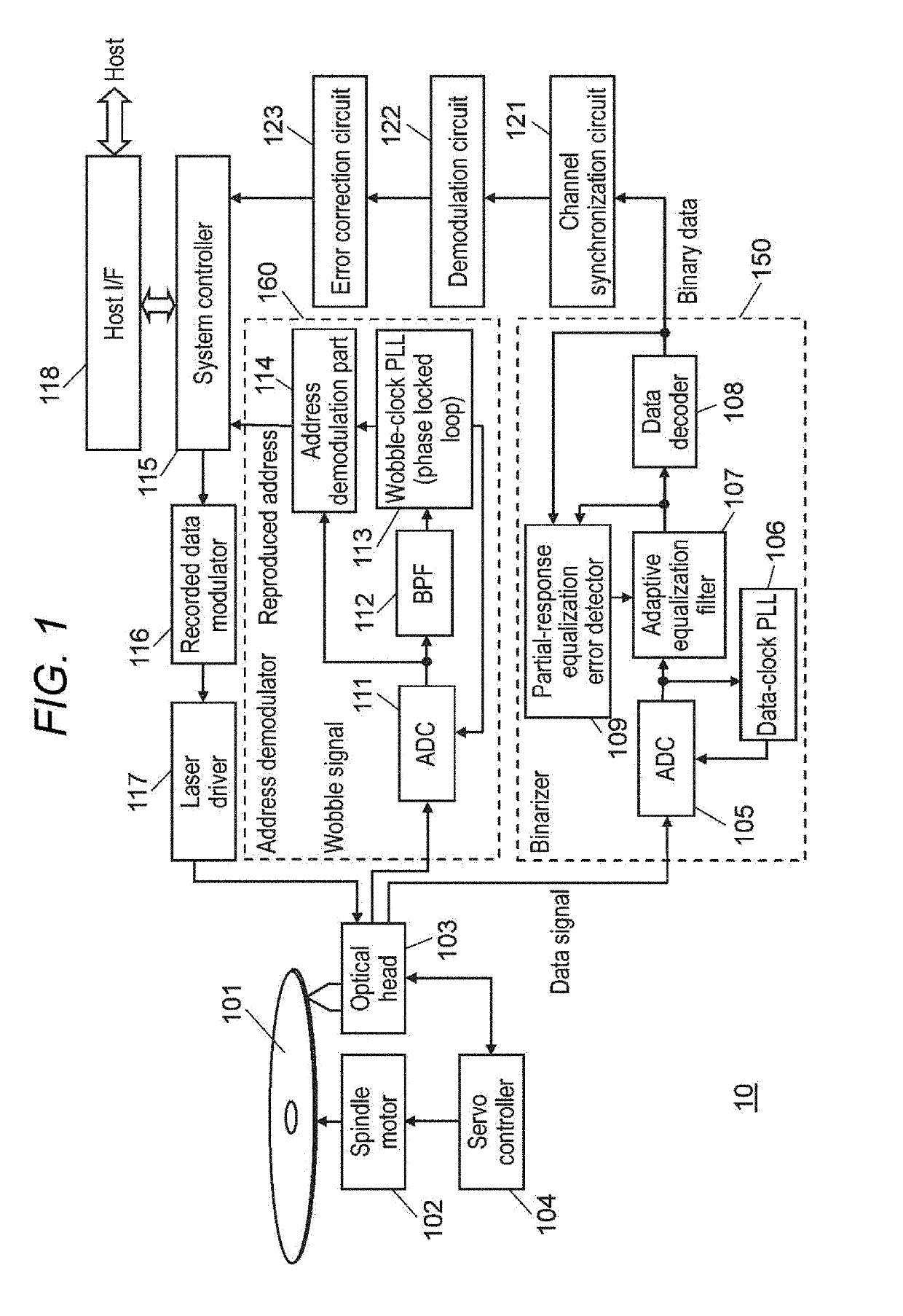
[0032]FIG. 1 is a diagram showing a configuration of an information recording / reproducing device of this exemplary embodiment, which records information to an optical disc and reproduces information from the optical disc.

[0033]Optical disc 101 has tracks formed into a spiral shape, in which information is recorded on the tracks. Moreover, wobbled grooves are formed on both sides of the tracks, and addresses which indicate physical positions on the optical disc are superimposed and recorded on the wobbled grooves.

[0034]Information recording / reproducing device 10 includes spindle motor 102, optical head 103, servo controller 104, binarizer 150, address demodulator 160, system controller 115, recorded data modulator 116, laser driver 117, host interface (host I / F) 118, channel synchronization circuit 121, demodulation circuit 122, and error correction circuit 123.

[0035]Optical head 103 irradiates optical...

second exemplary embodiment

[0125]The configuration and operation of a second exemplary embodiment will be described below. Descriptions for what are the same as in the first exemplary embodiment will be omitted, that is, only differences will be described below.

[0126]This exemplary embodiment will be described for a BD as an example optical disc whose recording layer has a three-layer structure and which has a recording capacity 100 GB. FIG. 13 shows that the wavelength of a laser light beam 170 incident on the optical disc is 405 nm, the numerical aperture (NA) of an object lens 171 is 0.85, and the length of a shortest recording mark (2 T) 173 among recording marks 172 having various lengths that are formed on a recording track is 111.5 nm. In this optical disc, the recording capacity per information recording layer is 33.4 GB.

[0127]An OTF (optical transfer function) cutoff frequency of this optical disc will be described below.

[0128]The OTF cutoff frequency is exceeded if the reference length T becomes so ...

third exemplary embodiment

[0141]The configuration and operation of a third exemplary embodiment will be described below. Descriptions for what are the same as in the first exemplary embodiment will be omitted, that is, only differences will be described below.

[0142]In the first exemplary embodiment, how to corrupt part of the data in an LDC block was described with reference to FIG. 7. In the example shown in FIG. 7, parity is provided for data of one vertical column (LDC codeword) in an LDC block and error correction using the parity is disabled by overwriting part of the data in the LDC block by paying attention to only the vertical one column.

[0143]This exemplary embodiment proposes that disables error correction reliably by overwriting part of the data for an error correction format having a structure that error correction parity includes internal parity PI extending in the recording direction and external parity PO extending in the direction perpendicular to the recording direction. The error correction...


PUM

PropertyMeasurementUnit
time seriesaaaaaaaaaa
lengthaaaaaaaaaa
lengthaaaaaaaaaa

Abstract

In an information recording device, when receiving an erase command by a receiver, a controller erases data of an erased area by overwriting data in an information area, to corrupt the data in the information area, using an erasing pattern. The erased area is specified by an erase start position and a size of the data to be erased on the optical disc. The data in the information area is arranged as partial data in a series of data arranged in a direction of internal parity of error correction so that correction is disabled in both of a correction processing by the internal parity of the error correction and a correction processing by external parity of the error correction when the data in the information area is overwritten using the erasing pattern.

Description

CROSS REFERENCE TO RELATED APPLICATIONS[0001]This application is based on Japanese Patent Application (No. 2018-039688) filed on Mar. 6, 2018, the contents of which are incorporated herein by reference.BACKGROUND1. Technical Field[0002]The present disclosure relates to a method and a device for erasing data recorded in a write-once optical disc.2. Description of Related Art[0003]The write-once optical disc is a recording medium that records information in an additional manner, in which data recorded once cannot be rewritten. However, from a viewpoint of preventing leakage of information, it is required that the data recorded in the write-once optical disc be erased. For such a request, Unexamined Japanese Patent Publication No. 2006-048763 discloses an erasing method of the data recorded in the write-once optical disc. In Unexamined Japanese Patent Publication No. 2006-048763, data, which is modulated by a modulation method of a same run length limit as a run length limit of a modul...

Claims


Application Information

Patent Timeline
Patent Type & Authority Applications(United States)
IPC IPC(8): G11B7/0037G11B7/0055
CPCG11B7/0055G11B7/0037G11B20/1833G11B2020/10851G11B20/1217G11B2020/10907G11B2220/218G11B7/0062G11B7/00555G11B7/00552G11B7/00557G11B7/006
Inventor MIYASHITA, HARUMITSUKIMURA, NAOHIRO
Owner PANASONIC INTELLECTUAL PROPERTY MANAGEMENT CO LTD
Why Eureka
Try Eureka