Negative pressure wound treatment apparatuses and methods with integrated electronics

a technology of negative pressure and wound treatment, applied in the field of negative pressure wound treatment apparatus, can solve the problems of cumbersome remote pump and tubing, difficult to integrate electronic components into the dressing, difficult to hide in or attach to patient clothing, etc., and achieve the effect of increasing the flexibility of the electronics cass

Pending Publication Date: 2019-09-19
SMITH & NEPHEW INC
View PDF2 Cites 16 Cited by
  • Summary
  • Abstract
  • Description
  • Claims
  • Application Information

AI Technical Summary

Benefits of technology

[0008]The wound dressing apparatus of the preceding paragraph or in other embodiments can include one or more of the following features. The electronic components can comprise one or more of a power source, a flexible circuit board, a sensor, a switch, and / or a light or LED indicator. The wound dressing apparatus can further comprise a negative pressure source inlet protection mechanism and a negative pressure source outlet or exhaust. The negative pressure source outlet or exhaust can comprise an antibacterial membrane and / or a non-return valve. The cover layer can comprise an aperture over the outlet or exhaust. The negative pressure source inlet protection mechanism can comprise a hydrophobic material configured to prevent fluid from entering the negative pressure source. The electronics cassette can comprise one or more slits, grooves or recesses in the casing, wherein the slits, grooves or recesses are configured to provide one or more hinge points in the casing and increase flexibility of the electronics cassette. The spacer layer can extend within both the first area and the second area and the electronics cassette is provided over the spacer layer. The negative pressure source and / or electronic components can be encapsulated in a hydrophobic coating.

Problems solved by technology

The remote pump and tubing can be cumbersome and difficult to hide in or attach to patient clothing.
Depending on the location of the wound dressing, it can be difficult to comfortably and conveniently position the remote pump and tubing.
When used, wound exudate may soak into the dressing, and the moisture from the wound has made it difficult to incorporate electronic components into the dressing.

Method used


Image

  • Negative pressure wound treatment apparatuses and methods with integrated electronics
  • Negative pressure wound treatment apparatuses and methods with integrated electronics
  • Negative pressure wound treatment apparatuses and methods with integrated electronics

Examples


Embodiment Construction

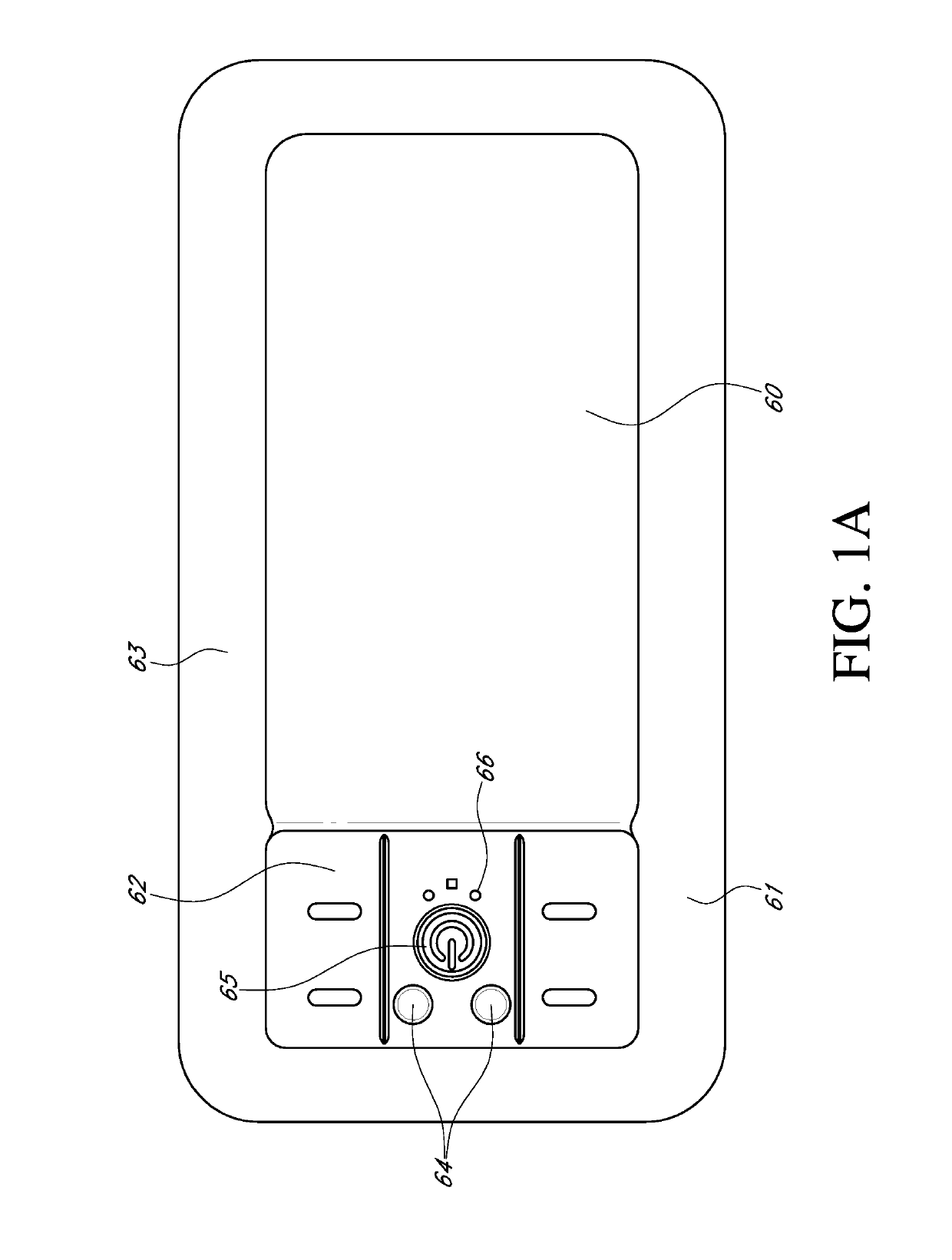
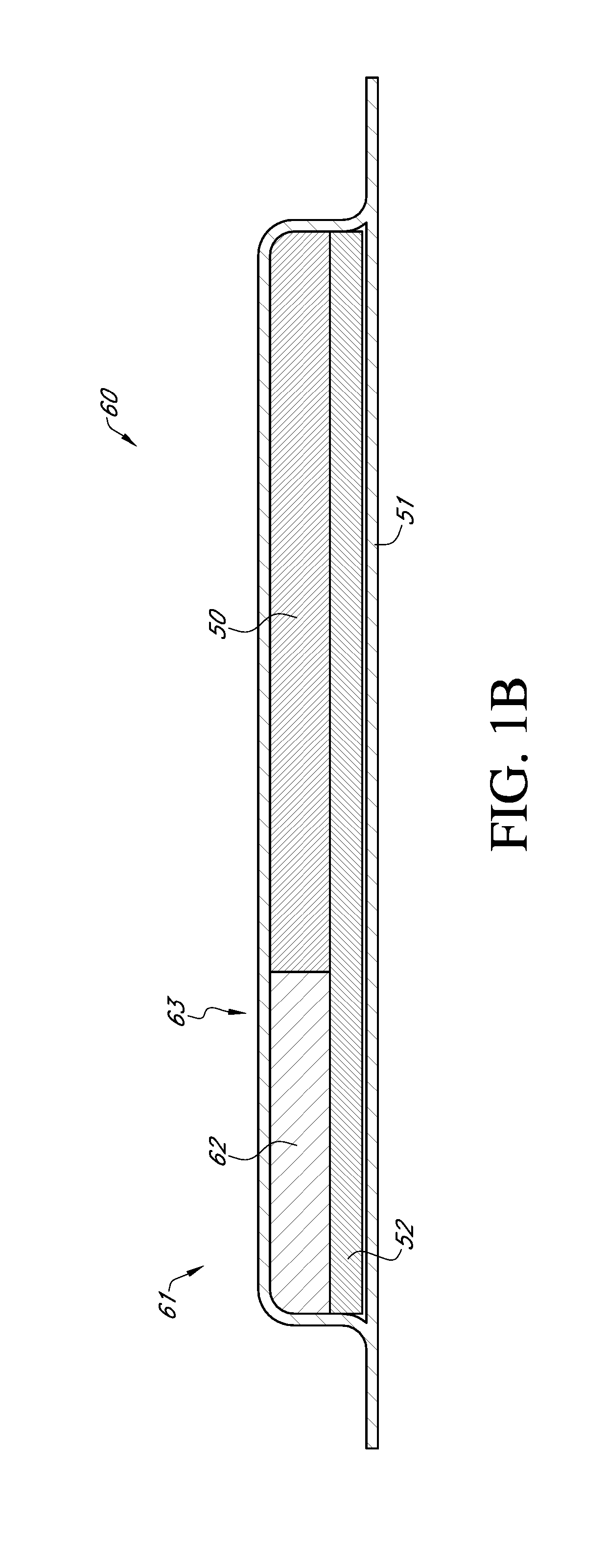
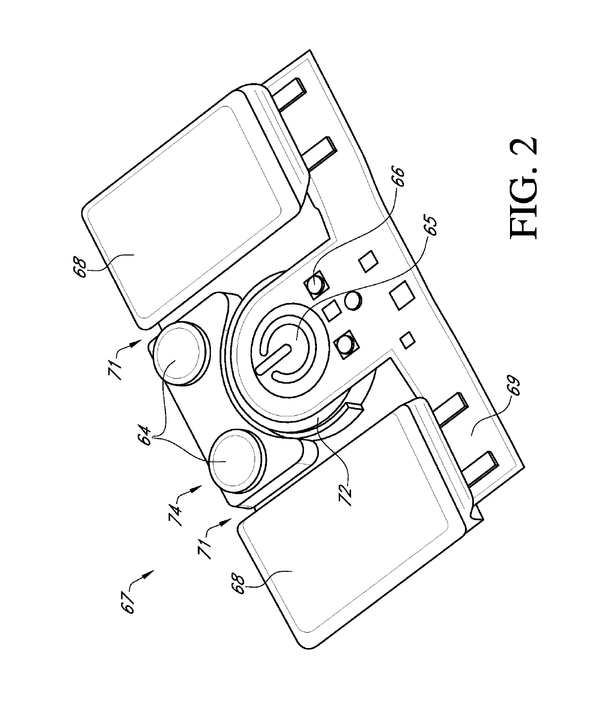
[0039]Embodiments disclosed herein relate to apparatuses and methods of treating a wound with reduced pressure, including a source of negative pressure and wound dressing components and apparatuses. The apparatuses and components comprising the wound overlay and packing materials, if any, are sometimes collectively referred to herein as dressings.

[0040]It will be appreciated that throughout this specification reference is made to a wound. It is to be understood that the term wound is to be broadly construed and encompasses open and closed wounds in which skin is torn, cut or punctured or where trauma causes a contusion, or any other superficial or other conditions or imperfections on the skin of a patient or otherwise that benefit from reduced pressure treatment. A wound is thus broadly defined as any damaged region of tissue where fluid may or may not be produced. Examples of such wounds include, but are not limited to, abdominal wounds or other large or incisional wounds, either a...


PUM


Abstract

Disclosed embodiments relate to apparatuses and methods for wound treatment. In some embodiments, a wound dressing apparatus can comprise a wound contact layer, a first area and a second area over the wound contact layer, and a cover layer configured to cover the wound contact layer, the first area, and the second area. The first area can comprise a spacer layer and an absorbent layer over the spacer layer. The second area can comprise an electronics cassette or cradle comprising a negative pressure source and/or electronic components.

Description

CROSS-REFERENCE TO RELATED APPLICATIONS[0001]This application claims priority to U.S. Provisional Patent Application No. 62 / 402,146, filed on Sep. 30, 2016, U.S. Provisional Patent Application No. 62 / 402,298, filed Sep. 30, 2016, and U.S. Provisional Patent Application No. 62 / 402,382, filed on Sep. 30, 2016. All of these applications are hereby incorporated by reference in their entireties and made part of this disclosure.BACKGROUNDTechnical Field[0002]Embodiments described herein relate to apparatuses, systems, and methods the treatment of wounds, for example using dressings in combination with negative pressure wound therapy.Description of the Related Art[0003]The treatment of open or chronic wounds that are too large to spontaneously close or otherwise fail to heal by means of applying negative pressure to the site of the wound is well known in the art. Negative pressure wound therapy (NPWT) systems currently known in the art commonly involve placing a cover that is impermeable o...

Claims


Application Information

Patent Timeline
Patent Type & Authority Applications(United States)
IPC IPC(8): A61M1/00A61F13/00A61F13/02
CPCA61F2013/8494A61M1/0092A61M1/009A61M2205/587A61F2013/8482A61M2205/583A61F13/0216A61M2205/7518A61F13/00068A61M2205/50A61M1/784A61M1/962A61M1/964
Inventor BEADLE, VICTORIAHESKETH, MARKKELBIE, WILLIAMMUSGRAVE, DAMYNROBINSON, JOSEPH WILLIAMSTEWARD, DANIEL
Owner SMITH & NEPHEW INC
Why Eureka
Try Eureka