
Separated-Wave Powered Electricity Gennerator

a technology of electricity generation and separated wave, which is applied in the direction of mechanical equipment, machines/engines, gearing, etc., can solve the problems of large pendulum pivot, low efficiency, and huge construction, and achieves low cost, high efficiency, and easy construction.

Active Publication Date: 2019-09-19
WU DIEN FOON
View PDF0 Cites 0 Cited by
  • Summary
  • Abstract
  • Description
  • Claims
  • Application Information

AI Technical Summary

Benefits of technology

The invention is a power generator that uses separated waves to produce electricity. It is efficient, easy to build, low-cost, and flexible. The generator consists of a floating platform unit that is isolated from large waves using a partition plate. The waves outside the plate move the platform unit up and down, which in turn drives power gears and external generators. The generator is designed to produce a single direction of rotation, which is then converted to electricity. The invention has the advantages of high efficiency, simple structure, easy installation, and can be fixed or offshore. It can be adjusted in size to meet different power needs. Overall, the invention provides a convenient, clean, and cheap source of electricity for all humanity.

Problems solved by technology

Drawbacks: A) The huge pendulum's pivot has to be fixed at a concreted structure, a huge construction B) low efficiency.
Low efficiency, high cost.
Low efficiency, low output, cannot provide electricity for commercial use.
Generally speaking, all the listed above and other methods such as Oscillating Water Column (OWC), Over Topping, Magnetic Fluid etc. are low efficiency, huge engineering, high cost, lack of construction flexibility, difficult to maintain, and low utilization rate on available sea area.

Method used


Image

  • Separated-Wave Powered Electricity Gennerator
  • Separated-Wave Powered Electricity Gennerator
  • Separated-Wave Powered Electricity Gennerator

Examples


Embodiment Construction

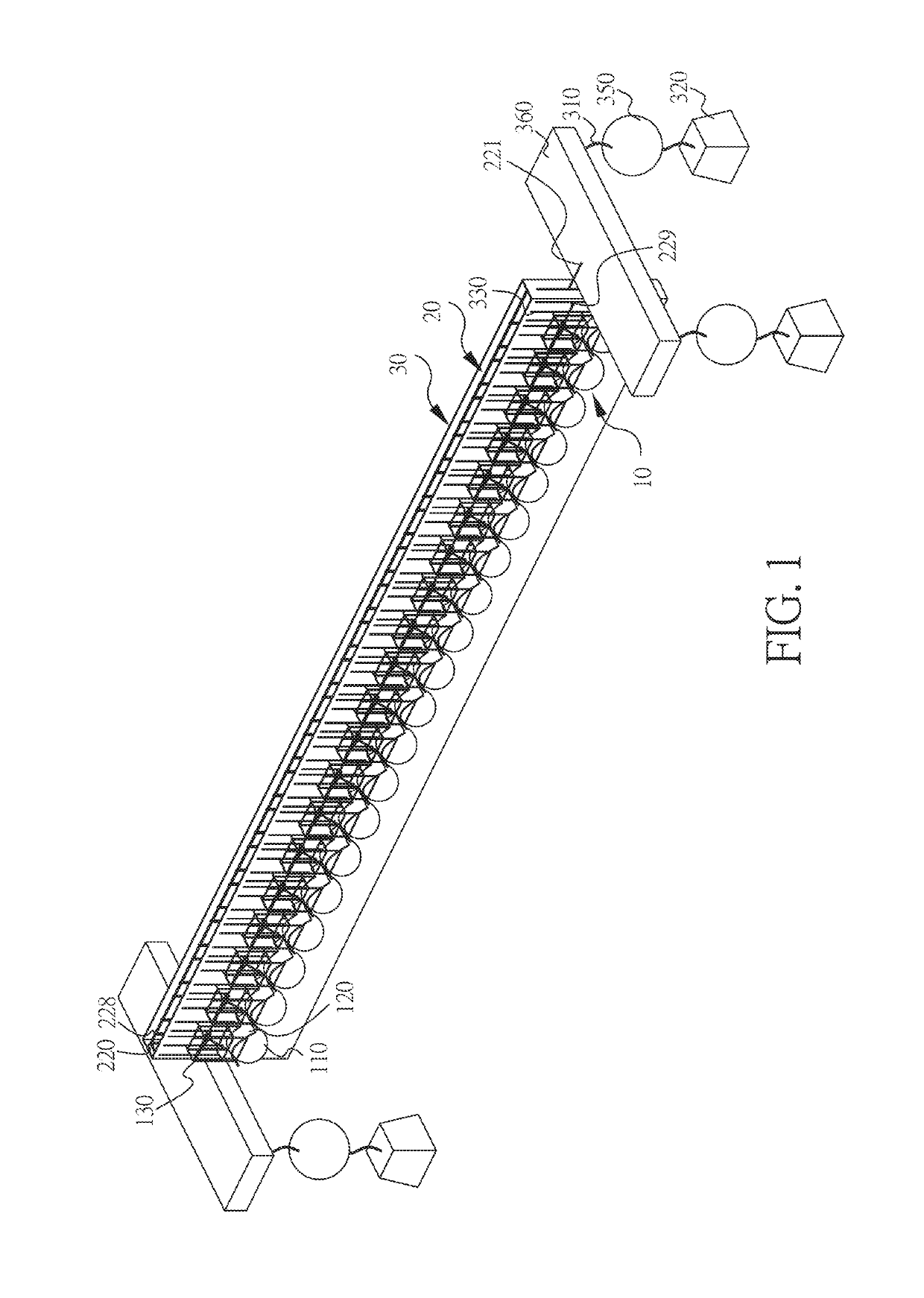
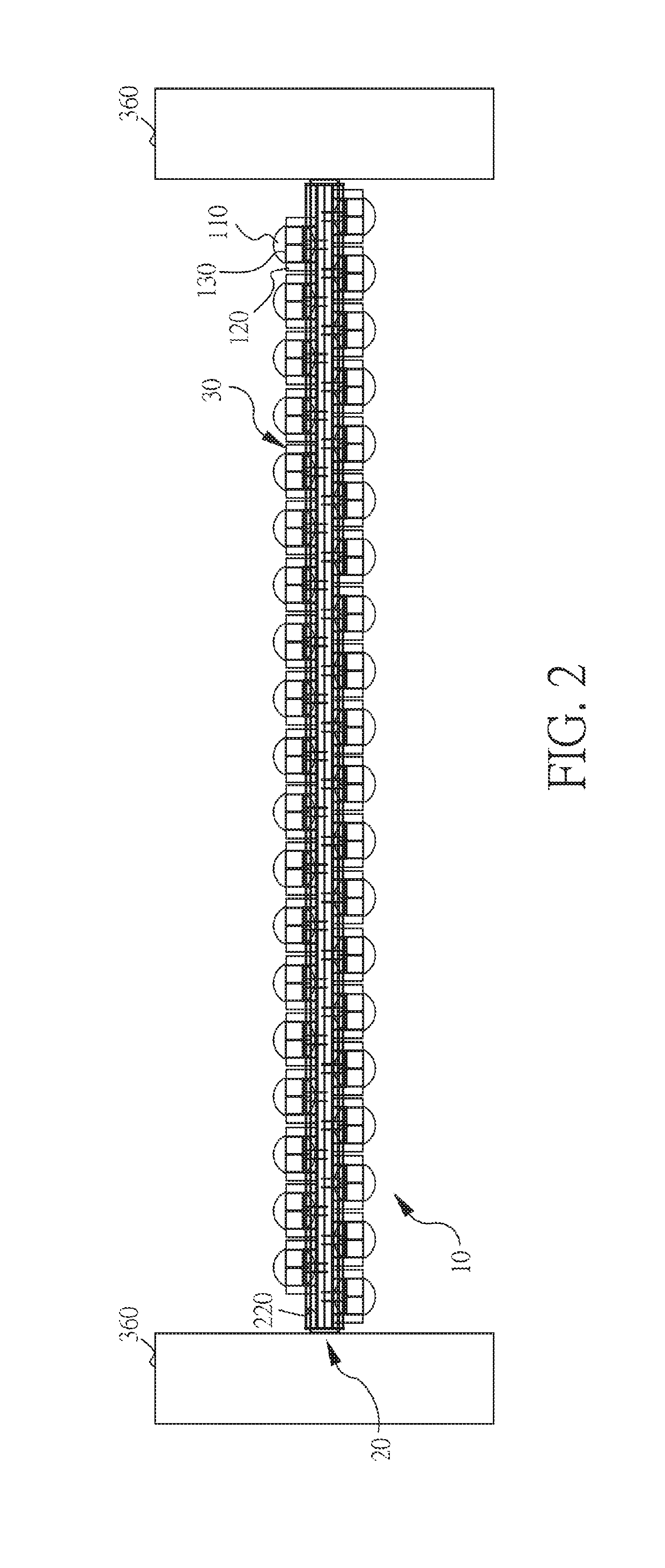
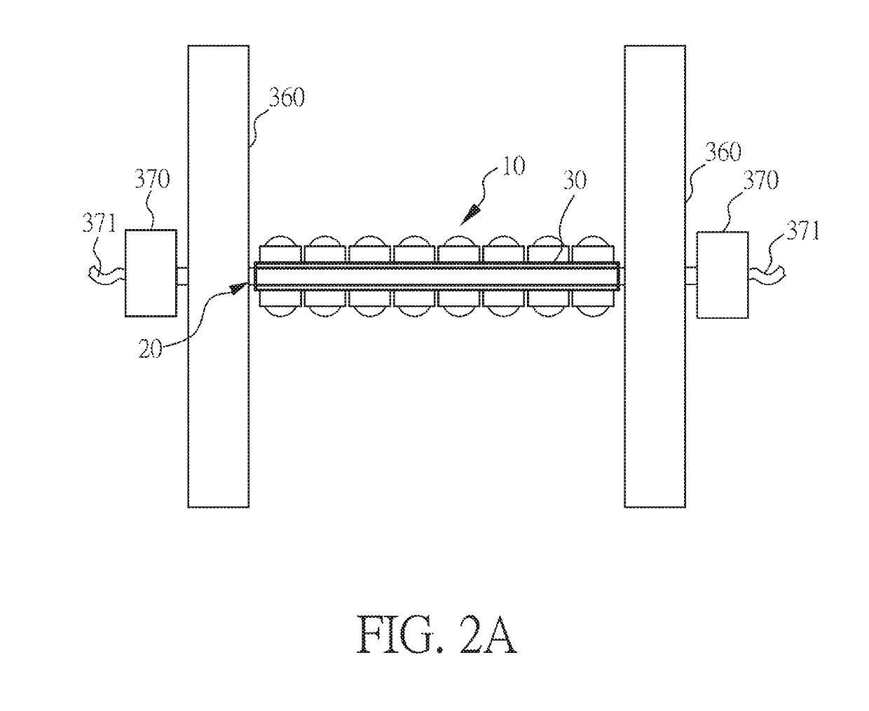
[0036]This invention is a separated-wave powered electricity generator. Basically, it comprises many pontoon units (10), one floating platform unit (20), and one partition plate unit (30). Referring to FIG. 1 through FIG. 16B, one of the embodiment examples is listed below:

[0037]Referring to FIG. 1-5, the floating platform unit (20) comprises a long and large floating platform (210) above which a supporting frame (220) is set up. This floating platform (210) is to lift up the supporting flame (220) above sea level. A central rotation shaft (221) is set up above the supporting flame (220). At each side of the central rotation shaft (221), a sideways rotation shaft (222) is set up. On each of the sideways rotation shaft (222), many dynamic gears (223) are set up. Each of the dynamic gear (223) is corresponding to one pontoon unit (10). Referring to FIG. 3, on dynamic gear's (223) right-hand side (as defined in FIG. 3.) is a ratchet gear (224) is set up. Corresponding to this ratchet g...


PUM


Abstract

This invention is a method in which large waves are separated from a floating platform unit by using a partition plate unit so that the floating platform unit enclosed by the partition plate unit is in a state of almost no wave. These large waves outside the partition plate unit are to move many floating ball units up and down so that the racks provided on each of the floating ball units are capable of rotating the power gears extending from the floating platform unit, and the rotational forces of power gears are regulated through ratchets and consolidated to produce a single direction rotating power, and then to drive external generators. The racks on the floating ball units and the power gears on the floating platform unit are pulled together by using springs. The resilient force of the two springs simultaneously helps the rack's ‘up and down’ in smooth reciprocating motion. Then the power gears directly and indirectly drive the multiple coaxial gear to output a single-direction spinning force to drive the external generators. The invention has the advantages of super high-efficiency, simple structure, easy to set up, able to be fixed or not fixed on the shore, and able to be set up offshore, and the size of the entire mechanism can be easily extended or adjusted linearly in terms of power demand. It can fully utilize the available sea area.

Description

FIELD OF THE INVENTION[0001]The present invention is related to a mechanism for generating electricity by using wave's undulation power, especially it applies the wave-separation method to isolate a waveless section from waves' intrusion in order to enhance efficiency and reduce construction cost.BACKGROUND[0002]Nowadays, to develop renewable energy become a trend and an important policy for all countries around the world and surely it will be more and more emphasized as time goes by because today's air-polluting energy resources will predictably run out in 140 years. In contrast, out of the sea area, 71% of total globe area, 2˜3 billion KW, the applicable sea-wave energy, is wasted every day. In the world, there are thousands of facilities using wave's undulation power to generate electricity. Nevertheless, in spite of the tremendous human and material resources invested by many countries to develop this sea-wave energy, none of them is truly efficient and economical.DESCRIPTION OF...

Claims


Application Information

Patent Timeline
Patent Type & Authority Applications(United States)
IPC IPC(8): F03B13/20F16H19/04F16H31/00F16H7/02
CPCF16H31/001F05B2240/93F03B13/20F16H7/023F05B2260/4031F16H19/04F03B13/186F05B2240/40F05B2260/4021F05B2260/505F16H7/02Y02E10/30
Inventor WU, DIEN-FOON
Owner WU DIEN FOON
Learn More