Dc-dc converter and control method

a converter and control method technology, applied in the direction of electric variable regulation, process and machine control, instruments, etc., can solve the problems of reducing transformer temperature and conduction loss, and achieve the effect of improving power conversion efficiency

Active Publication Date: 2019-09-19
ABB (SCHWEIZ) AG
View PDF0 Cites 27 Cited by
  • Summary
  • Abstract
  • Description
  • Claims
  • Application Information

AI Technical Summary

Benefits of technology

[0017]Preferably, during power transfer from the first converter circuit to the second converter circuit: the first converter circuit and the first resonant tank are operable in series resonant conversion of converting an input voltage into an immediate voltage for input to the second resonant tank; and the second resonant tank and the second converter circuit are operable in series resonant conversion of the immediate voltage to provide an output voltage. This provides the DC to DC converter with functionality of bi-directional conversion that not only allows for a full control of the output voltage in both direction of power transfer, but when properly dimensioned, can provide ZVS for the first converter circuit and the second converter circuit in for...

Problems solved by technology

As a result, the resonant current becomes smaller, which causes decrease of conduction losses.
Moreover, since a small magnetizing inductance becomes unn...

Method used


Image

  • Dc-dc converter and control method
  • Dc-dc converter and control method
  • Dc-dc converter and control method

Examples


Embodiment Construction

[0025]While the invention is susceptible to various modifications and alternative forms, specific embodiments thereof are shown by way of example in the drawings and will herein be described in detail. It should be understood, however, that the drawings and detailed description thereto are not intended to limit the invention to the particular form disclosed, but on the contrary, the intention is to cover all modifications, equivalents, and alternatives falling within the spirit and scope of the present invention as defined by the appended claims. Note, the headings are for organizational purposes only and are not meant to be used to limit or interpret the description or claims. Furthermore, note that the word “may” is used throughout this application in a permissive sense (i.e., having the potential to, being able to), not a mandatory sense (i.e., must).” The term “include”, and derivations thereof, mean “including, but not limited to”. The term “connected” means “directly or indire...


PUM


Abstract

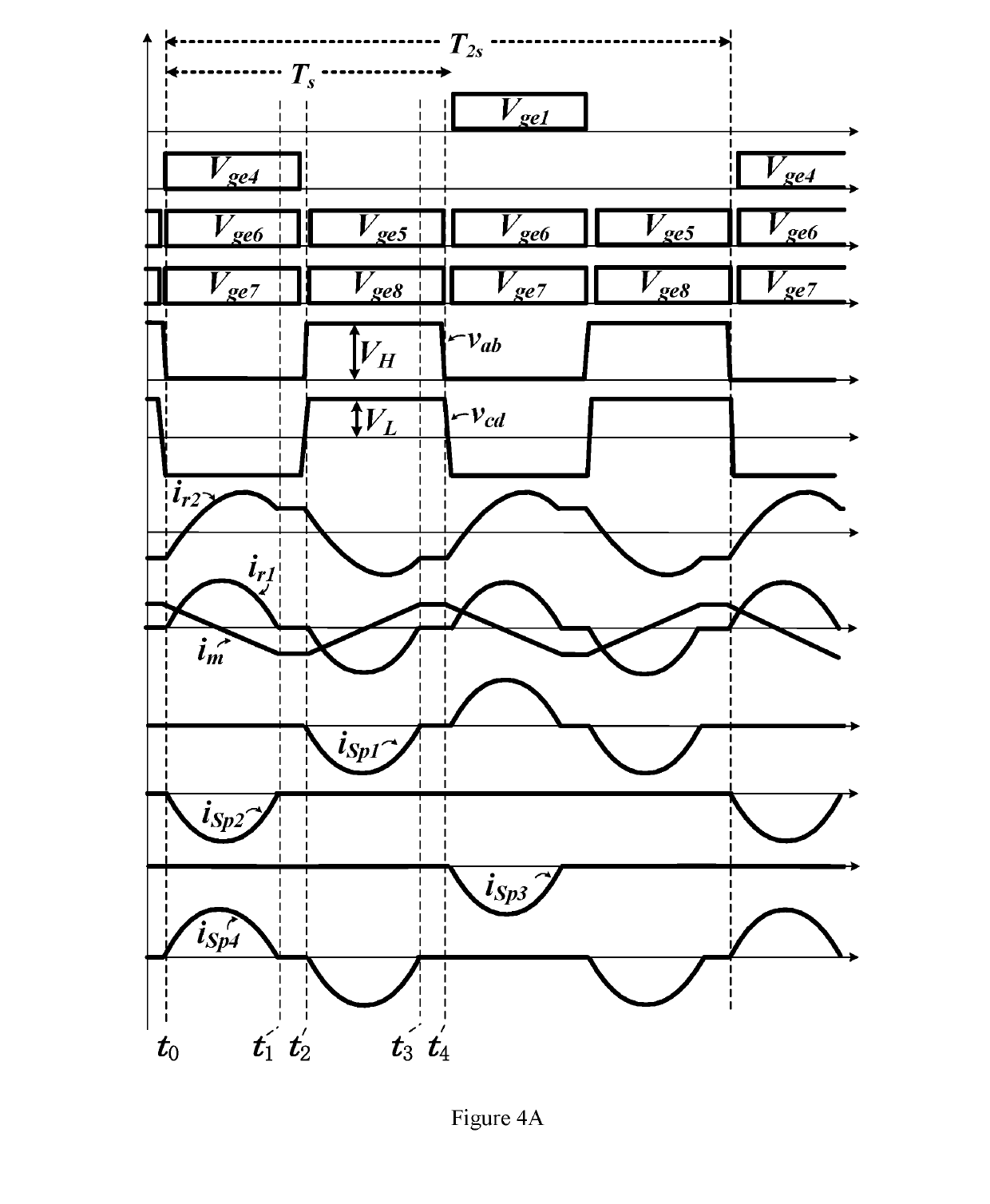
The application relates to a DC to DC converter and control method thereof. The DC to DC converter includes a first converter circuit, a second converter circuit, a transformer having a primary winding and a secondary winding, a first resonant tank having a first capacitive element and a first inductive element, and a second resonant tank having a second capacitive element and a second inductive element. The first capacitive element and the first inductive element are coupled between the first converter circuit and the primary winding of the transformer; the second capacitive element and the second inductive element are coupled between the second converter circuit and the secondary winding of the transformer. During power transfer from the second converter circuit to the first converter circuit, a first plurality of first power-semiconductor-devices of the first converter circuit are operable to charge the first capacitive element during a first half cycle of a switching period; and a second plurality of the first power-semiconductor-devices of the first converter circuit are operable to provide an output voltage comprising an voltage across the primary winding of the transformer and the voltage of the first capacitive element superimposed thereon. This provides step-up gain for the backward direction, the first converter circuit operating in double voltage rectification manner and the second converter circuit working in the conventional full-bridge modulation with switching frequency fixed substantially at the resonant frequency.

Description

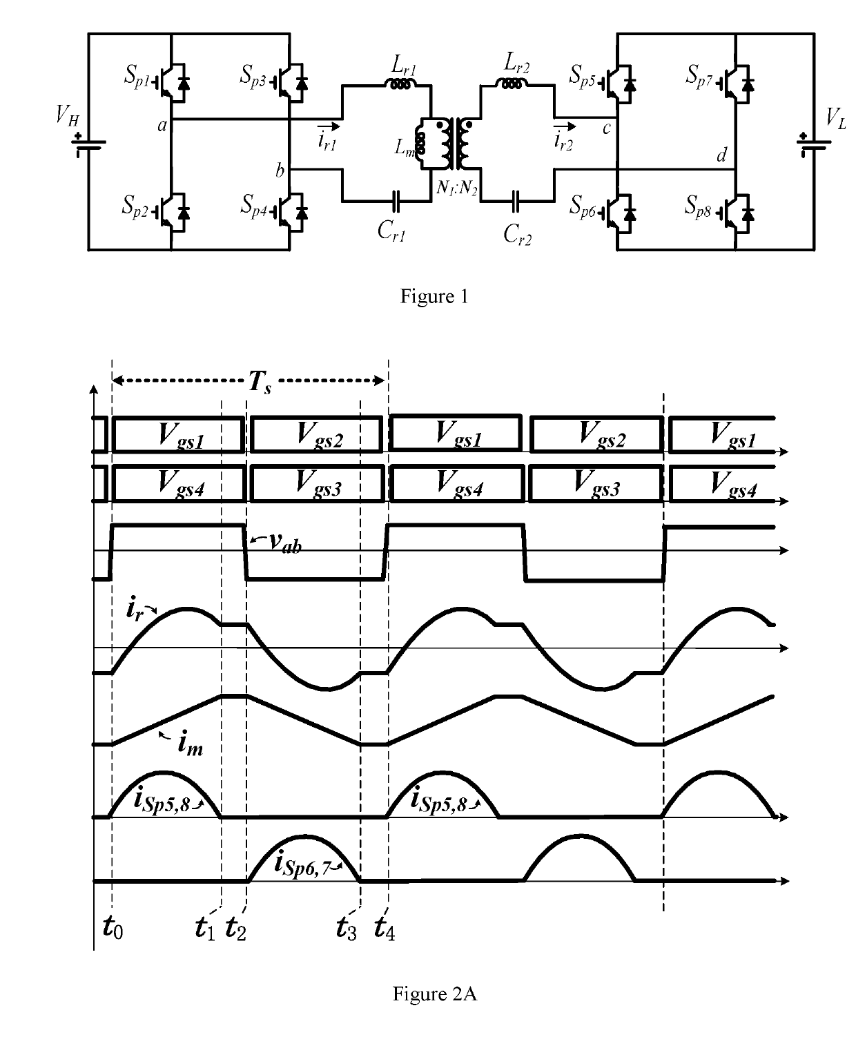
TECHNICAL FIELD[0001]The invention relates to conversion of DC power input into DC power output, and more particularly to DC to DC conversion with intermediate conversion into AC.BACKGROUND ART[0002]Conventional wide-range bidirectional resonant converters are generally classified into two types: two-stage structure, and one stage with online parameter change. In the former type, one additional conversion stage is dedicatedly added to extend the voltage gain range, while the original stage has little voltage regulation capability. In the latter type, multiple voltage gain ranges can be generated by changing the converter parameters, including resonant component parameters or transformer turn ratio.[0003]FIG. 1 shows a topology of conventional bidirectional DC / DC resonant converter. As shown in FIG. 1, VH and VL are the voltages of the two DC ports of the converter. Due to the topological symmetry, the converter operations in the two power transferring directions are the same. To sim...

Claims


Application Information

Patent Timeline
IPC IPC(8): H02M3/335H02M1/08
CPCH02M3/33584H02M1/083H02M2001/0058Y02B70/10H02M1/0003H02M1/0058H02M3/33573H02M3/01
Inventor ZONG, SHENGYANG, XIAOBOFAN, GUOXINGYAO, DAWEI
Owner ABB (SCHWEIZ) AG
Why Eureka
Try Eureka