Process and plant for the thermal abatement of malodorous emission from a purification plant with energy recovery from said abatement

a technology of purification plant and energy recovery, which is applied in the direction of specific water treatment objectives, water treatment parameter control, biochemistry apparatus, etc., can solve the problems of high cost, waste water and/or digestate purification process requires a significant amount of energy, and the use of methane gas boilers involves the consumption of huge amounts of fuel

Active Publication Date: 2019-09-26
VOMM IMPIANTI E PROCESSI
View PDF0 Cites 1 Cited by
  • Summary
  • Abstract
  • Description
  • Claims
  • Application Information

AI Technical Summary

Benefits of technology

[0053]Therefore, the abatement process according to the present invention may allow heating of a high-temperature heat-exchange liquid and transfer thereof to a drier of a purification plant,

Problems solved by technology

This air deodorization technique involves however the use of a large quantity of chemical substances, resulting in very high costs.
Secondly, it is evident how a waste water and/or digestate purification process requires a significant amount of energy, in particular in the form of thermal energy for heating both the tanks inside which biological treatment is

Method used


Image

  • Process and plant for the thermal abatement of malodorous emission from a purification plant with energy recovery from said abatement
  • Process and plant for the thermal abatement of malodorous emission from a purification plant with energy recovery from said abatement
  • Process and plant for the thermal abatement of malodorous emission from a purification plant with energy recovery from said abatement

Examples


Embodiment Construction

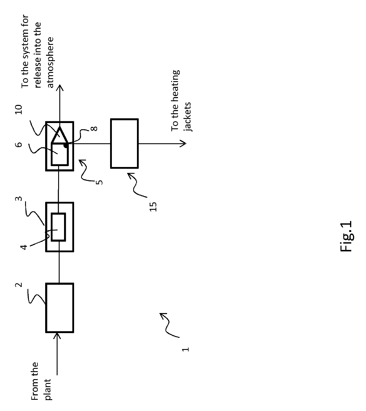
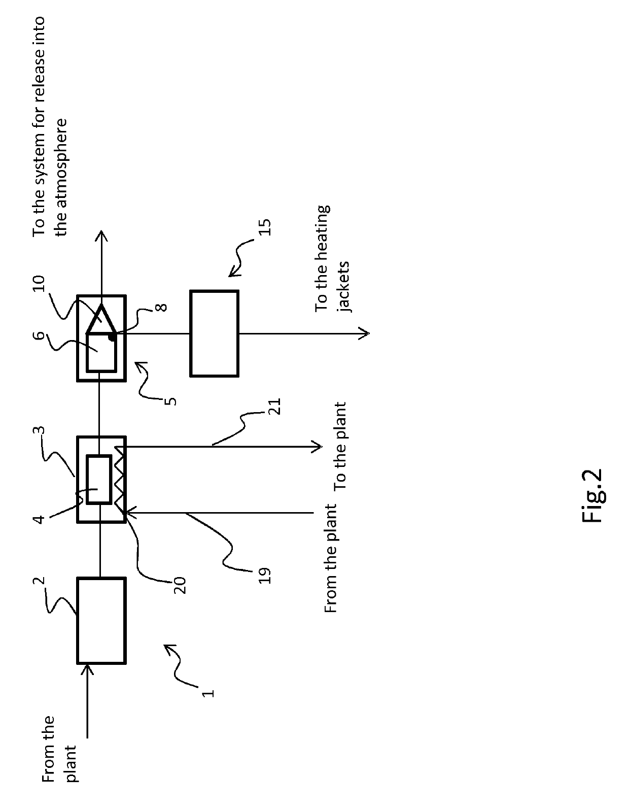
[0079]FIG. 1 shows a system 1, indicated overall by 1, for the thermal abatement of malodorous emissions from a purification plant with energy recovery from said abatement, which implements the process according to a mode of implementation of the present invention; this system comprises the following units:[0080]a pipe 2 for collecting foul air containing malodorous substances coming from a purification plant;[0081]a unit 3 for the production and recovery of energy comprising a combustion chamber 4 in fluid communication with the aforesaid collecting pipe 2;[0082]a scrubber 5 for polluting substances in fluid communication with the said combustion chamber, said scrubber 5 is fed with water for washing an exhaust gas flow exiting from the combustion chamber and comprises an abatement chamber 6, a discharge opening 8 for a washing liquid and a flow conveyor 10 for a purified and cooled exhaust gas flow;[0083]a distribution header 15 for a washing liquid in fluid communication with the...


PUM

PropertyMeasurementUnit
Temperatureaaaaaaaaaa

Abstract

A process and a plant for the thermal abatement of foul air containing malodorous substances emitted by a purification system with energy recovery from said abatement are described, the process comprising the steps of: —feeding a flow of foul air containing malodorous substances emitted from a purification plant, as combustive air into the combustion chamber of a unit for production and recovery of energy, thus producing a flow of high-temperature exhaust gas; —feeding said flow of exhaust gas into a scrubber for the abatement of polluting substances, said scrubber using water for the washing of the flow of exhaust gas, thus producing a flow of low-temperature purified gas and a heated washing liquid; —conveying the heated washing liquid to at least one heating jacket of a storage tank for the biological treatment of sewage of the aforementioned purification plant; a method for revamping a pre-existing purification plant, so as to make the plant suitable for implementation of the process described above, is also described.

Description

FIELD OF APPLICATION[0001]The present invention relates to a process for the thermal abatement of malodorous emissions from a purification plant with energy recovery from said abatement.[0002]According to one aspect of the present invention, this process is applied to malodorous emissions from a plant for the treatment of urban or industrial waste waters and / or digestates. The invention also relates to a system for implementing the aforementioned process as well as to a method for revamping a conventional purification plant in order to make it suitable for implementing the aforementioned method.PRIOR ART[0003]It is well-known in the art that the disposal of waste waters from urban sewers and / or industrial discharge outlets, and the treatment of digestates, in both an industrial and an agricultural environment, are of fundamental importance in the context of sustainable urban development, from both an environmental and an economic point of view.[0004]In particular, the waste waters m...

Claims


Application Information

Patent Timeline
IPC IPC(8): B01D53/34B01D53/76B01D53/75B01D53/18B01D53/14C02F3/30C02F11/04B01D53/38
CPCC02F2303/10C02F2303/02C02F11/04B01D2258/02B01D53/38B01D53/343B01D2252/103C02F3/302B01D53/1425C02F2209/02B01D53/75B01D53/18B01D53/76C02F2103/18B01D53/78B01D2257/90B01D2258/05C12M43/04Y02W10/30Y02E50/30Y02W10/20
Inventor VEZZANI, MASSIMO
Owner VOMM IMPIANTI E PROCESSI
Why Eureka
Try Eureka