Current sensor

a current sensor and sensor technology, applied in the field of current sensors, can solve the problems of generating leakage magnetic field from the end of the magnetic plate, affecting the electromagnetic conversion element, etc., and achieve the effect of reducing the generation of leakage magnetic field and high accuracy

Active Publication Date: 2019-09-26
DENSO CORP
View PDF0 Cites 9 Cited by
  • Summary
  • Abstract
  • Description
  • Claims
  • Application Information

AI Technical Summary

Benefits of technology

[0010]It is a first object of the present disclosure to provide a current sensor capable of reducing a leakage magnetic field and preventing the influence of the leakage magnetic field due to magnetic saturation. It is a second object of the present disclosure to provide a current sensor capable of detecting a current with high accuracy.
[0013]As thus described, the current sensor is formed by the two base portions in the magnetic shield being coupled to each other by the coupling portion, so that it is possible to reduce the leakage magnetic field from the end of the base portion. That is, in the current sensor, the leakage magnetic field from the end of the base portion can be reduced as compared to the case where two base portions are not coupled by the coupling portion and are divided.
[0014]In addition, with the recess being formed in the magnetic shield, the current sensor causes the magnetic flux generated from the current path to flow on the surface of the magnetic shield opposite to the facing region of the magnetic shield. For this reason, in the current sensor, the side opposite to the facing region of the magnetic shield, namely, the side of the magnetic shield farther from the magnetic detection element tends to be saturated magnetically. Therefore, the current sensor can prevent the leakage magnetic field due to magnetic saturation of the magnetic shield from affecting the magnetic detection element.
[0017]At least one of the first end phase shield and the second end phase shield includes a magnetic field exchanger configured to perform magnetic field exchange between the first end phase shield and the second end phase shield such that a leakage magnetic field from an extreme end of one of the first end phase shield and the second end phase shield in the arrangement direction reaches the other of the first end phase shield and the second end phase shield more easily than the end phase detection element.
[0018]As thus described, according to the second aspect of the present disclosure, at least one of the first end phase shield and the second end phase shield includes the magnetic field exchanger. Thus, in the present disclosure, the leakage magnetic field from the extreme end in the arrangement direction of each of the first end phase shield and the second end phase shield more easily reaches each of the first end phase shield and the second end phase shield on the other facing side, than the end phase detection element. Therefore, in the present disclosure, the leakage magnetic field can be prevented from reaching the end phase detection element, and the current can be detected with high accuracy.
[0022]As thus described, according to the third aspect of the present disclosure, the current sensor includes the magnetic field exchanger that is provided continuously with the ends of the first end phase shield and the second end phase shield in the arrangement direction to integrate the first end phase shield and the second end phase shield. Thus, the present disclosure can reduce generation of the leakage magnetic field from the end in the arrangement direction of the first end phase shield and the second end phase shield. Therefore, in the present disclosure, the leakage magnetic field can be prevented from reaching the end phase detection element, and the current can be detected with high accuracy.

Problems solved by technology

For this reason, in the current detection system, there is the possibility that a leakage magnetic field is generated from the end of the magnetic plate.
Therefore, in the current detection system, a leakage magnetic field from the magnetic plate due to magnetic saturation tends to affect the electromagnetic conversion element.

Method used


Image

  • Current sensor
  • Current sensor
  • Current sensor

Examples


first embodiment

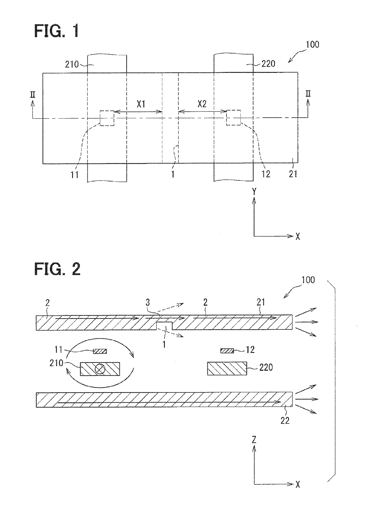
[0069]With reference to FIGS. 1 and 2, a current sensor 100 of a first embodiment will be described. The current sensor 100 is used, for example, for controlling an inverter of an in-vehicle motor. The current sensor 100 detects a current to be detected that flows in bus bars 210, 220 connected to an in-vehicle battery which supplies power to the in-vehicle motor, so as to control the inverter. The bus bars 210, 220 correspond to the current paths.

[0070]The current sensor 100 is used, for example, in an electric vehicle or a hybrid vehicle. As the current sensor 100, for example, it is possible to employ a careless current sensor that does not require a magnetism collecting core.

[0071]The current sensor 100 includes a first magnetic detection element 11, a second magnetic detection element 12, a first magnetic shield 21, and a second magnetic shield 22.

[0072]For example, it is possible to employ a configuration for each of the first magnetic detection element 11 and the second magne...

seventh modification

[0130]With reference to FIG. 9, a current sensor 107 of the seventh modification will be described. The current sensor 107 differs from the current sensor 100 in a structure of a first magnetic shield 21G. FIG. 9 is a sectional view corresponding to FIG. 2.

[0131]The current sensor 107 includes a first magnetic shield 21G and a second magnetic shield 22G. The second magnetic shield 22F is similar to the second magnetic shield 22E, and thus a description thereof will be omitted.

[0132]In the first magnetic shield 21G, the recess 1 is formed in each of the vicinity of the first bus bar 210 and the vicinity of the second bus bar 220. More specifically, the recess 1 is formed at each of a position that the first bus bar 210 faces and a position that the second bus bar 220 faces. That is, the recess 1 is formed at a position facing each of the magnetic detection elements 11, 12. The first magnetic shield 21G is provided with a heat radiation gel 40 in the recess 1. The heat radiation gel 4...

eighth modification

[0135]With reference to FIGS. 10 and 11, a current sensor 108 of the eighth modification will be described. The current sensor 108 differs from the current sensor 100 in a structure of a first magnetic shield 21G. Further, the current sensor 108 differs from the current sensor 100 in being configured as a sensor for four phases. FIG. 10 is a sectional view corresponding to FIG. 2.

[0136]The current sensor 108 includes a first sensor block 108A, a second sensor block 108B, a third sensor block 108C, and a fourth sensor block 108D. The current sensor 108 is constructed by assembling a plurality of sensor blocks 108A to 108D. Moreover, the current sensor 108 can be said to be modularized by connecting the plurality of sensor blocks 108A to 108D. Each of the sensor blocks 108A to 108D has a same configuration.

[0137]With reference to FIG. 11, the configuration of each of the sensor blocks 108A to 108D will be described here. A description will be given using the first sensor block 108A as...


PUM


Abstract

A current sensor includes a magnetic detection element that senses a magnetic flux generated from a current path to perform electromagnetic conversion, and at least two magnetic shields that are arranged around the magnetic detection element and shield an external magnetic flux affecting the magnetic detection element. The at least two magnetic shields include a first magnetic shield and a second magnetic shield facing each other across the magnetic detection element and the current path. At least one of the first magnetic shield and the second magnetic shield includes at least two base portions and a coupling portion coupling the at least two base portions. The at least one of the first magnetic shield and the second magnetic field has a recess recessed from a periphery in a surface facing the other of the first magnetic shield and the second magnetic shield.

Description

CROSS REFERENCE TO RELATED APPLICATION[0001]This application is based on Japanese Patent Application No. 2016-119135 filed on Jun. 15, 2016, Japanese Patent Application No. 2016-226096 filed on Nov. 21, 2016, and Japanese Patent Application No. 2016-240590 filed on Dec. 12, 2016, the disclosures of which are incorporated herein by reference.TECHNICAL FIELD[0002]The present disclosure relates to a current sensor that senses a magnetic flux generated from a current path to perform electromagnetic conversion, and a current sensor that senses a magnetic field generated from the current path and converts the magnetic field into an electric signal to detect a current flowing in the current path.BACKGROUND ART[0003]As a current sensor, there has been a current detection system disclosed in Patent Literature 1. The current detection system has magnetic plates, and a bus bar and a semiconductor substrate corresponding to the magnetic plates. On the semiconductor substrate, an electromagnetic...

Claims


Application Information

Patent Timeline
Patent Type & Authority Applications(United States)
IPC IPC(8): G01R33/09G01R19/25
CPCG01R19/25G01R33/091G01R15/20G01R15/207G01R33/0017G01R33/0076G01R33/072G01R33/093G01R33/096G01R33/098
Inventor ESAKA, TAKUMANOMURA, KOHSUKESAKAI, RYOSUKESUGITO, TATSUAKI
Owner DENSO CORP
Why Eureka
Try Eureka