Multilayer coil component
a coil and component technology, applied in the direction of inductance of fixed capacitor details, inductance with magnetic core, etc., can solve the problems of large stray capacitance due to the electrode, inability to achieve satisfactory radio frequency characteristics, and inability to support operation in the above-mentioned radio frequency range. achieve the effect of improving radio frequency characteristics
- Summary
- Abstract
- Description
- Claims
- Application Information
AI Technical Summary
Benefits of technology
Problems solved by technology
Method used
Image
Examples
example 1
[0123](1) A ferrite raw material (calcined powder) having a predetermined composition was prepared.
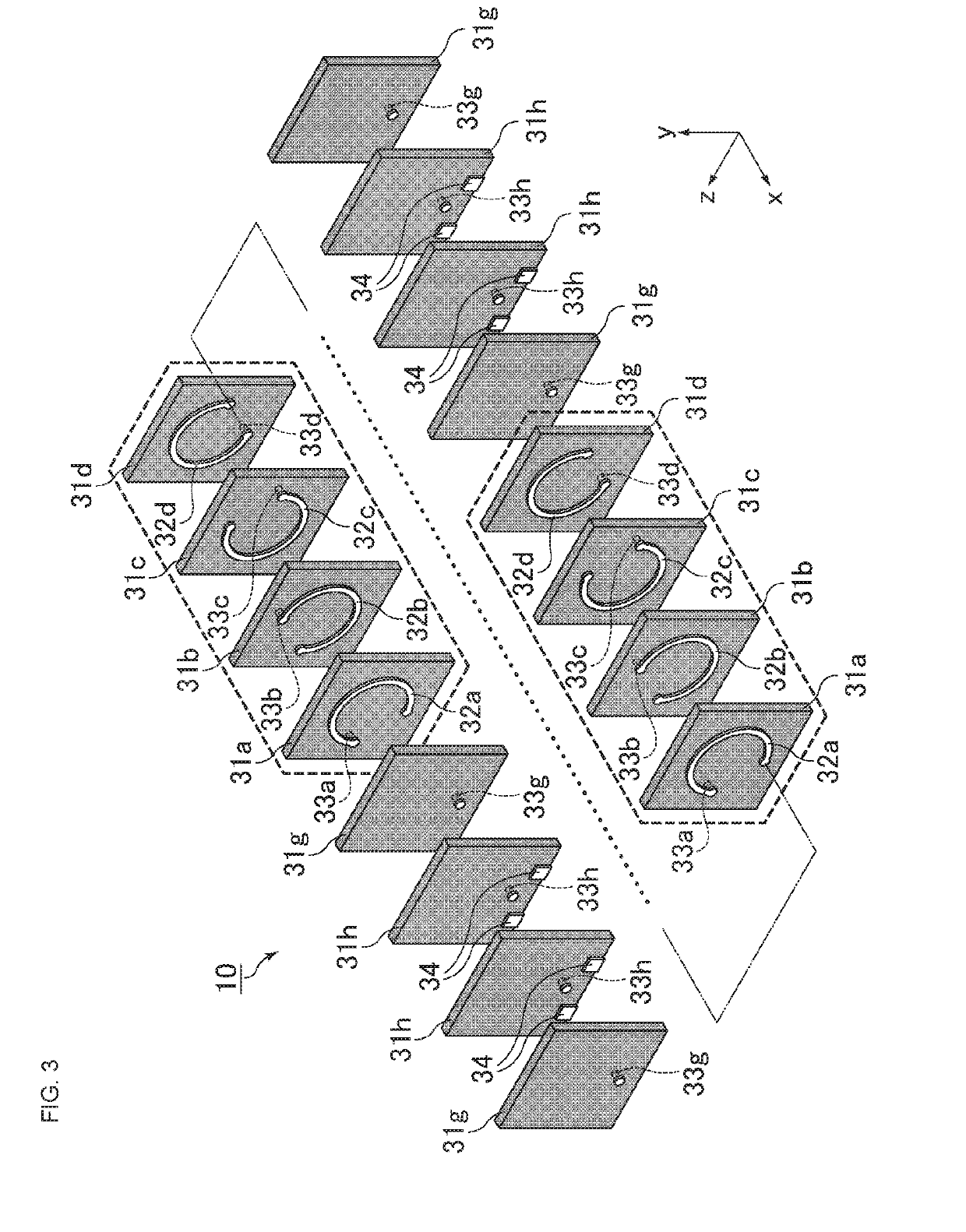
[0124](2) The calcined powder, an organic binder (polyvinyl butyral-based resin), and an organic solvent (ethanol and toluene) were charged into a pot mill together with PSZ balls, and sufficiently mixed and ground in a wet method to produce a magnetic material slurry.
[0125](3) The magnetic material slurry was formed into a substantially sheet-like shape by the doctor-blade method, which was then punched in a rectangular shape to produce a plurality of magnetic material sheets with a thickness of about 15 μm.
[0126](4) A conductive paste containing Ag powder and organic vehicle and used for forming an inner electrode was prepared.
[0127](5) Fabrication of Via Sheets
[0128]A predetermined part of the magnetic material sheet was irradiated with a laser beam to form a via hole. A conductive paste was applied to fill the via hole, followed by screen printing with a conductive paste applied in...
example 2
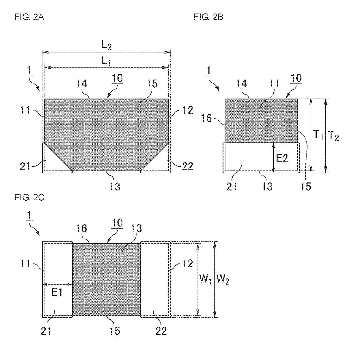
[0140]Samples according to Example 2 were fabricated by changing the number of stacked coil sheets that form coil conductors, and the number of stacked via sheets that form connecting conductors, and by changing the thickness of the magnetic material sheet constituting each coil sheet and each via sheet. The dimensions of the multilayer body, and the shape of each outer electrode were identical to those in Example 1.
examples 3 and 4
[0152]Simulation 1 of Transmission Coefficient S21: Connecting-Conductor Length
[0153]For each multilayer coil component fabricated under the conditions given below, the relationship between frequency and transmission coefficient S21 was simulated.
[0154]The results are illustrated in Table 1 and FIG. 9 as follows:
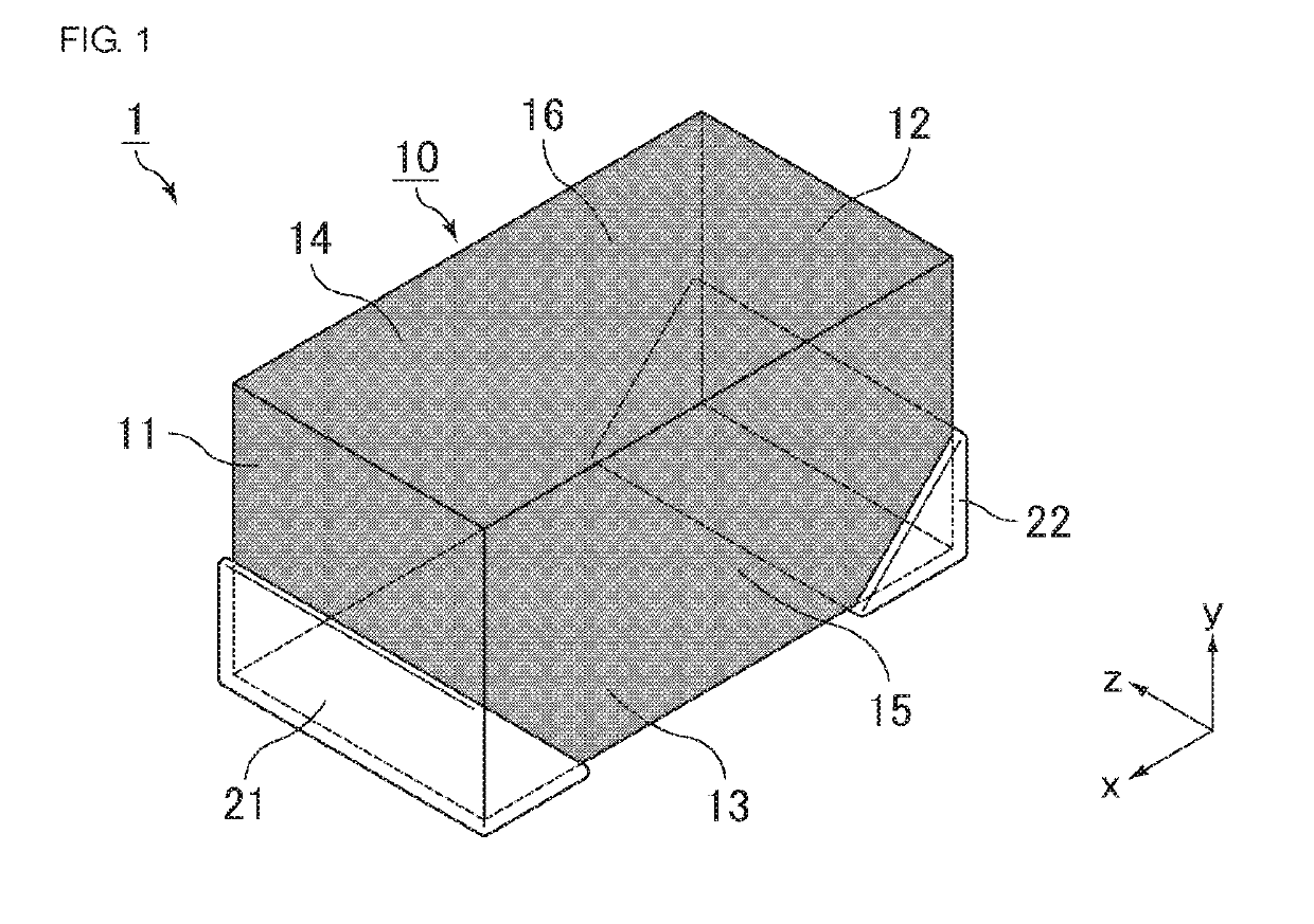
[0155]Width of the multilayer body: 300 μm
[0156]Length of the coil: 510 μm
[0157]Number of coil conductor turns: 42
[0158]Inner diameter of each coil conductor: 100 μm
[0159]Line width of each coil conductor: 60 μm
[0160]Film thickness of each coil conductor: 4 μm
[0161]Distance between the coil conductors (thickness of each insulating layer): 5 μm
[0162]Length of each connecting conductor: 20 or 45 μm
[0163]Width of each connecting conductor: 30 μm
[0164]Width of the land constituting each connecting conductor: 80 μm
TABLE 1Example 3Example 4Length [%] of each of first and second connecting7.5%3.6%conductors relative to length of multilayer bodyTransmission coefficient S21 [dB] at 4...
PUM
| Property | Measurement | Unit |
|---|---|---|
| length | aaaaa | aaaaa |
| width | aaaaa | aaaaa |
| height | aaaaa | aaaaa |
Abstract
Description
Claims
Application Information
 - R&D
- Intellectual Property
- Life Sciences
- Materials
- Tech Scout
- Unparalleled Data Quality
- Higher Quality Content
- 60% Fewer Hallucinations
Browse by: Latest US Patents, China's latest patents, Technical Efficacy Thesaurus, Application Domain, Technology Topic, Popular Technical Reports.
© 2025 PatSnap. All rights reserved.Legal|Privacy policy|Modern Slavery Act Transparency Statement|Sitemap|About US| Contact US: help@patsnap.com


