Neutralization of phase perturbations from deterministic electromagnetic interference

Active Publication Date: 2019-10-03
SKYWORKS SOLUTIONS INC
View PDF1 Cites 2 Cited by
  • Summary
  • Abstract
  • Description
  • Claims
  • Application Information

AI Technical Summary

Benefits of technology

The invention relates to methods for reducing jitter in output clock signals generated by clock generators. The methods involve neutralizing periodic phase perturbations in the oscillating signals using opposing periodic phase perturbations, which can be achieved by adjusting the duty cycle of the output clock signal or by adding an auxiliary signal to the oscillator. These methods can provide more stable and accurate output clock signals with reduced jitter, which can be useful in various applications such as communication systems.

Problems solved by technology

Injection of energy by an output driver into the oscillator that generates the signal being driven causes a periodic disturbance in the phase trajectory of the oscillator, and introduces spurs in the output signal, thereby reducing performance.
For example, spurs (i.e., deterministic jitter) in clock signals used in an exemplary wireless communications system reduce an opening in an eye diagram (i.e., eye pattern) for digital signals at a receiver and degrade performance of the wireless communications system.
Spurs generate energy outside of a target frequency band that may affect adjacent channels and may cause energy outside of a frequency band of interest to frequency shift down to an intermediate frequency of the communications system, and thus degrade a signal-to-noise ratio for the communications system.
Shielding of the oscillator from the periodic disturbance may be limited by integrated circuit design, manufacturing, and packaging constraints.

Method used


Image

  • Neutralization of phase perturbations from deterministic electromagnetic interference
  • Neutralization of phase perturbations from deterministic electromagnetic interference
  • Neutralization of phase perturbations from deterministic electromagnetic interference

Examples


Embodiment Construction

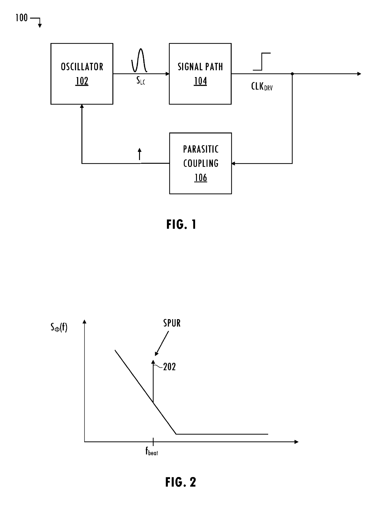
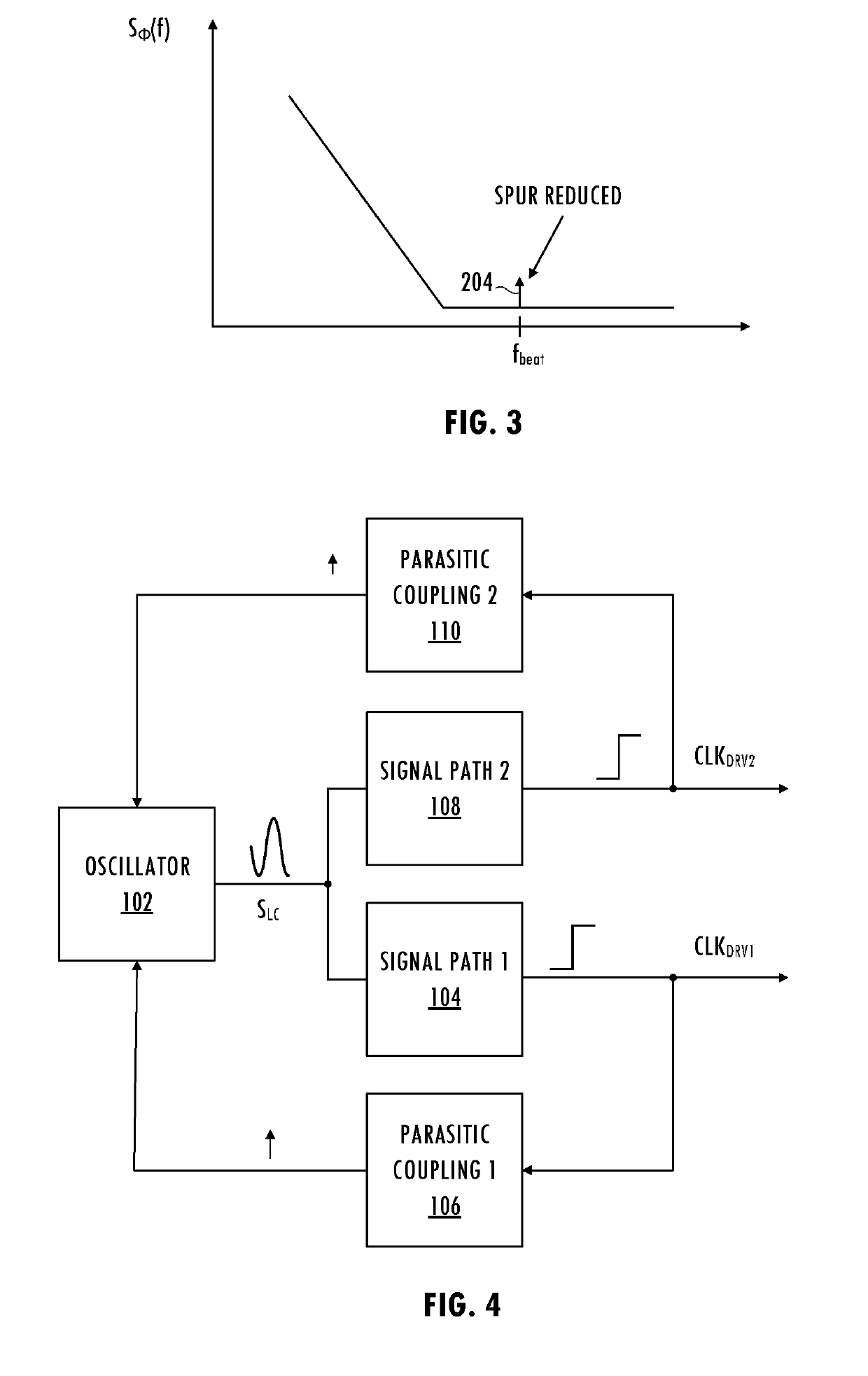
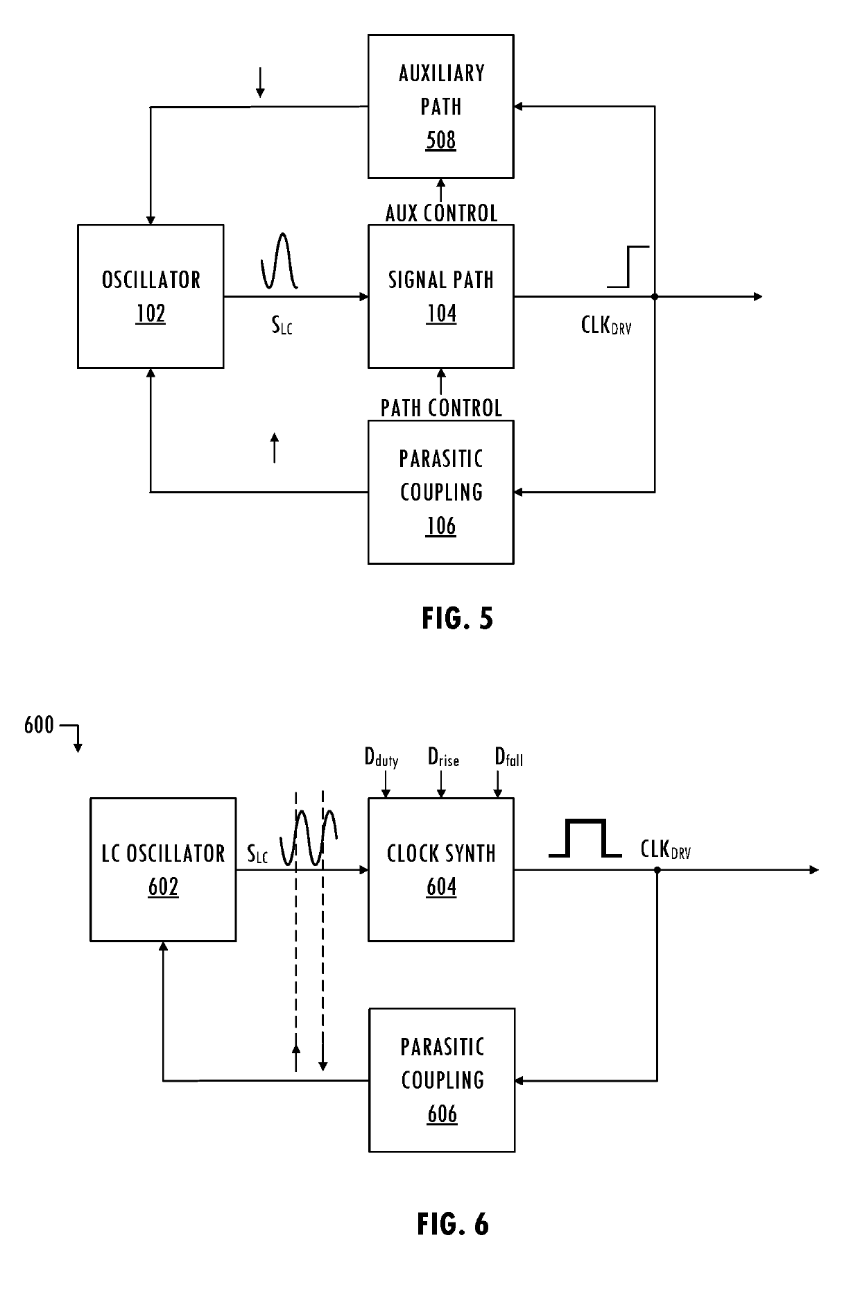
[0003]In at least one embodiment of the invention, a clock generator includes an oscillator configured to generate an oscillating signal and a signal path configured to provide an output clock signal based on the oscillating signal. In response to a control signal, the clock generator is configured to neutralize periodic phase perturbations in the oscillating signal using opposing periodic phase perturbations. The neutralization may occur in the signal path. The signal path may be responsive to the control signal to adjust at least one of a duty cycle, a rise time, and a fall time of the output clock signal to cause alternating phase perturbations of the periodic phase perturbations to apply as the opposing periodic phase perturbations in the output clock signal. The neutralization may occur in the oscillator. The clock generator may include an auxiliary path configured to provide an auxiliary signal to the oscillator. The auxiliary signal may be configured according to the control ...


PUM


Abstract

A clock generator includes an oscillator configured to generate an oscillating signal and a signal path configured to provide an output clock signal based on the oscillating signal. In response to a control signal, the clock generator is configured to neutralize periodic phase perturbations in the oscillating signal using opposing periodic phase perturbations. The neutralization may occur in the signal path. The signal path may be responsive to the control signal to adjust at least one of a duty cycle, a rise time, and a fall time of the output clock signal to cause alternating phase perturbations of the periodic phase perturbations to apply as the opposing periodic phase perturbations in the output clock signal. The neutralization may occur in the oscillator. The clock generator may include an auxiliary path configured to provide an auxiliary signal to the oscillator.

Description

BACKGROUNDField of the Invention[0001]The present application relates to integrated circuits, and more particularly to integrated circuits that include oscillators.Description of the Related Art[0002]Driving an oscillating signal off-chip generates a time-varying magnetic field that extends into the surrounding environment. That time-varying magnetic field can inject energy into neighboring circuitry. Injection of energy by an output driver into the oscillator that generates the signal being driven causes a periodic disturbance in the phase trajectory of the oscillator, and introduces spurs in the output signal, thereby reducing performance. For example, spurs (i.e., deterministic jitter) in clock signals used in an exemplary wireless communications system reduce an opening in an eye diagram (i.e., eye pattern) for digital signals at a receiver and degrade performance of the wireless communications system. Spurs generate energy outside of a target frequency band that may affect adja...

Claims


Application Information

Patent Timeline
IPC IPC(8): H03L7/093H04L7/033H03L7/087H03L7/091H05K1/02
CPCH05K1/0216H03L7/093H03L7/087H04L7/033H03L7/091H03B5/1206H03B5/32H03B2200/009H03B2202/076H03L7/00
Inventor CAFFEE, AARON J.CROMAN, RUSSELLDROST, BRIAN G.
Owner SKYWORKS SOLUTIONS INC
Why Eureka
Try Eureka