
Autogenous Cooling Method for In Space Storage and Transfer of Cryogenic Rocket Propellants

a technology of rocket propellant and autogenous cooling, which is applied in the operation mode of machines, cosmonautic vehicles, lighting and heating apparatus, etc., can solve the problems of failure of cryocoolers or insufficient power to run them continuously, affecting the efficiency of the system, so as to increase the cooling capacity and system efficiency

Inactive Publication Date: 2019-10-10
CHANCERY WILLIAM JACOB +1
View PDF2 Cites 5 Cited by
  • Summary
  • Abstract
  • Description
  • Claims
  • Application Information

AI Technical Summary

Benefits of technology

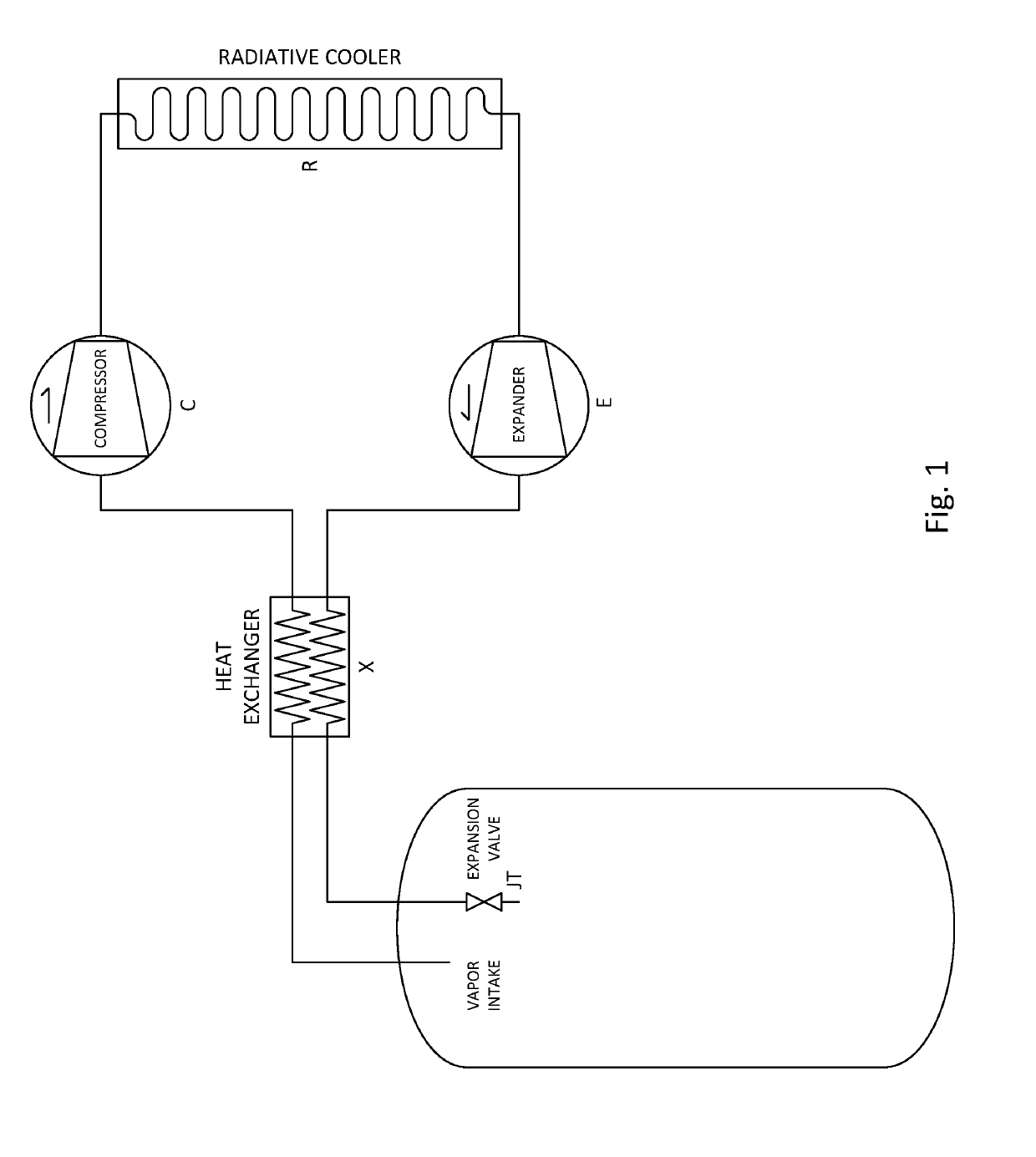
The patent describes a cooling system that uses a cryogenic fluid as the refrigerant and a compressor to push the fluid through a cooling element and a thermal expansion valve back into a storage tank. An expander increases the cooling capacity and system efficiency, and a crossflow heat exchanger transfers heat energy from the fluid to the compressor's flow. This system can be used in a closed loop phase change system to achieve tank chilldown without losing fluid. It allows for efficient cooling of warm tanks by using the cryogenic fluid as a refrigerant.

Problems solved by technology

To minimize inert system mass, bulk storage tanks are not designed to contain propellant pressure at equilibrium temperature.
It also means that when the cryocoolers are not operational for any reason, they introduce an additional heat leak path.
So a system with failed cryocoolers or insufficient power to run them continuously may actually lose cryogenic fluid to boil off faster than a system without active cooling.
Although these systems benefit in having fluid interfaces which can more easily be used to interface the cold end of the coolant circuit with the storage tank or the warm end with the heat rejector without needing an additional heat transfer circuit (Broad Area Cooling), they still use a separate refrigerant fluid and lines and therefore increase system mass, failure risk, and complexity.
There are two main problems with in space transfer of cryogenic fluids.

Method used


Image

  • Autogenous Cooling Method for In Space Storage and Transfer of Cryogenic Rocket Propellants
  • Autogenous Cooling Method for In Space Storage and Transfer of Cryogenic Rocket Propellants
  • Autogenous Cooling Method for In Space Storage and Transfer of Cryogenic Rocket Propellants

Examples


Embodiment Construction

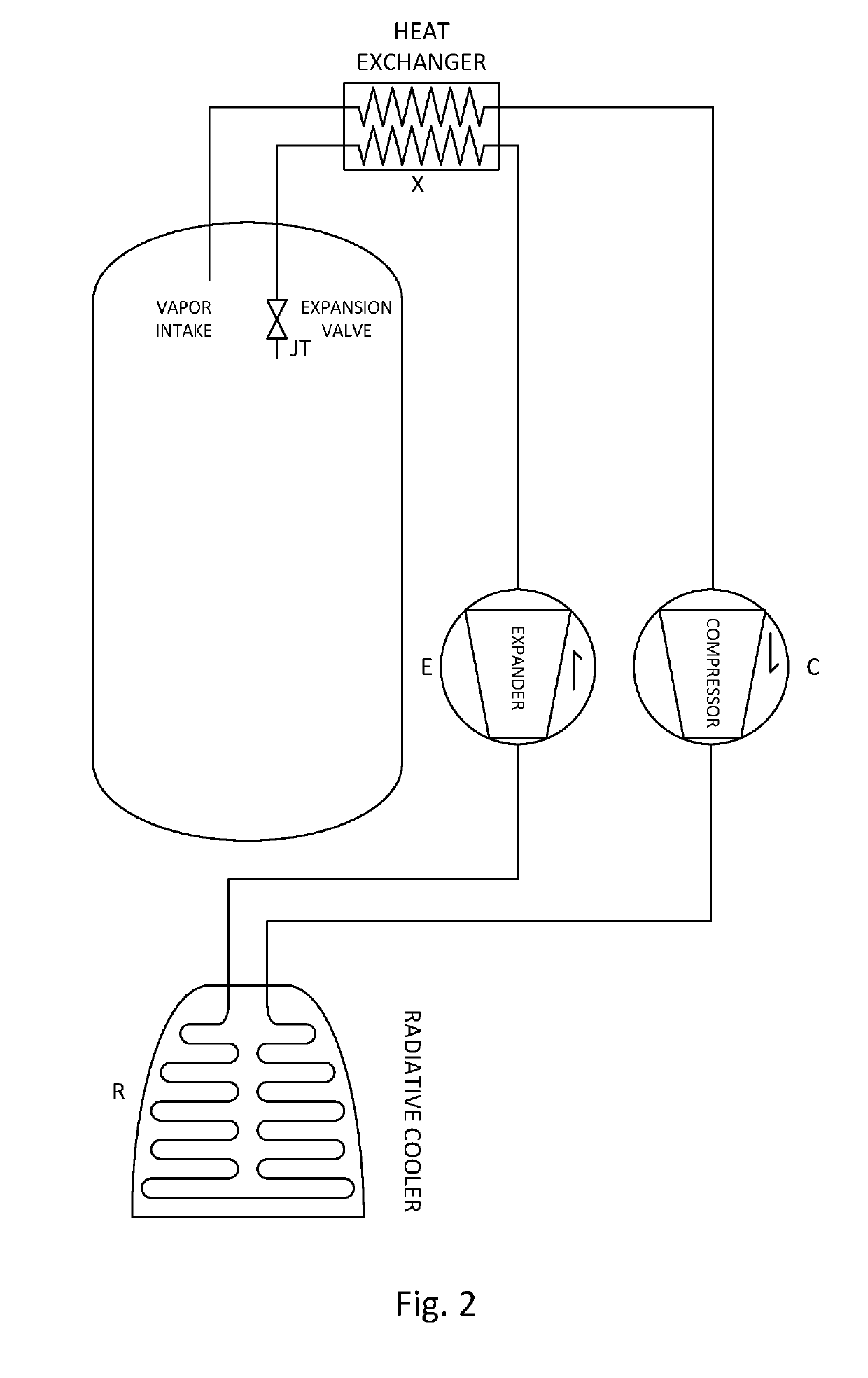
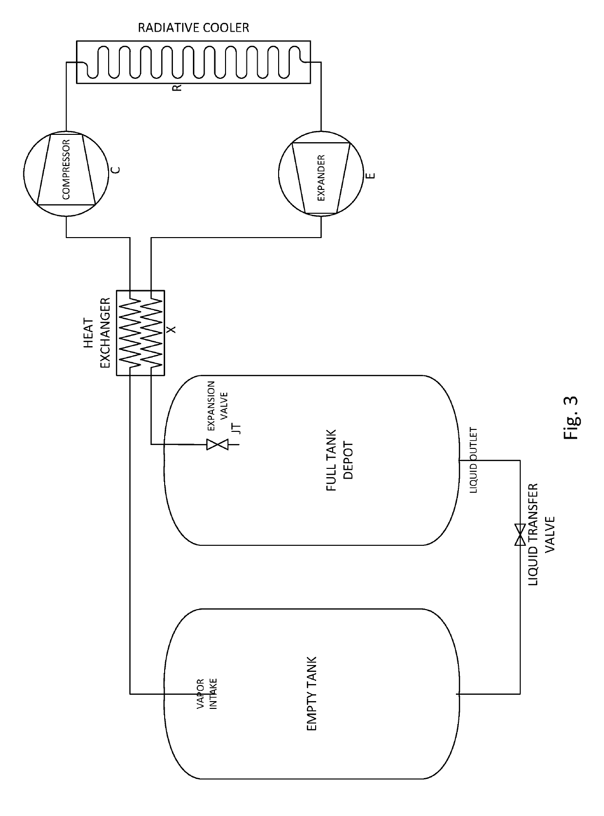
[0012]A compressor (C) draws propellant vapor from the tank through a heat exchanger (X) which increases the vapor temperature. The compressor increases the flow pressure and the outlet stream flows through a radiative cooling element (R) where it rejects heat energy to space. The fluid returning from the cooling element flows through an expander element (E) where some of the pressure energy in the flow is recovered. The work output from this compressor may be used to partially power the compressor, increasing overall system efficiency. From there the fluid passes through the other side of the heat exchanger, which further lowers its temperature, before entering the final pressure reducing valve (JT). This final flow restriction, or Joule-Thomson device, induces some amount of condensation in the fluid stream re-entering the storage vessel.

[0013]Many liquid propellant rocket engines utilize a regenerative cooling system. This cooling method directs cryogenic propellant through parts...


PUM


Abstract

The present invention refers to a cryogenic cooling system utilizing rocket propellant as the working fluid in a phase change closed loop process. The purpose of the system is to enable long term zero boil off storage of cryogenic liquid rocket propellant in space. The system will also enable transfer of cryogenic liquid from one tank volume to another in a propellant depot mode of operation.

Description

BACKGROUND OF THE INVENTIONField of the Invention[0001]This invention relates to the field of cryogenic liquid propellant storage and transfer for space travel and exploration.Description of Related Art[0002]There is always some heat load coming into a storage tank, even in the vacuum of space. To minimize inert system mass, bulk storage tanks are not designed to contain propellant pressure at equilibrium temperature. Therefore, storage tanks are equipped with pressure relief valves which allow excess vapor pressure to vent. One part of a strategy to minimize liquid boil off loss is to minimize the heat load into the tank. This passive method is accomplished with radiative shielding to block sunlight and thermal standoffs to minimize heat load from structural elements that must not be at cryogenic liquid temperatures.[0003]The other part of a boil off minimization strategy is active cooling. This is typically done with self-contained cryocooler units and associated radiative cooling...

Claims


Application Information

Patent Timeline
Patent Type & Authority Applications(United States)
IPC IPC(8): F25B19/00B64G1/40
CPCB64G1/401F25B19/005F25B2400/12F25B40/00F25B9/02F25B9/06B64G1/402B64G1/50
Inventor CHANCERY, WILLIAM JACOBISHERWOOD, CLAYTON M.
Owner CHANCERY WILLIAM JACOB
Learn More