

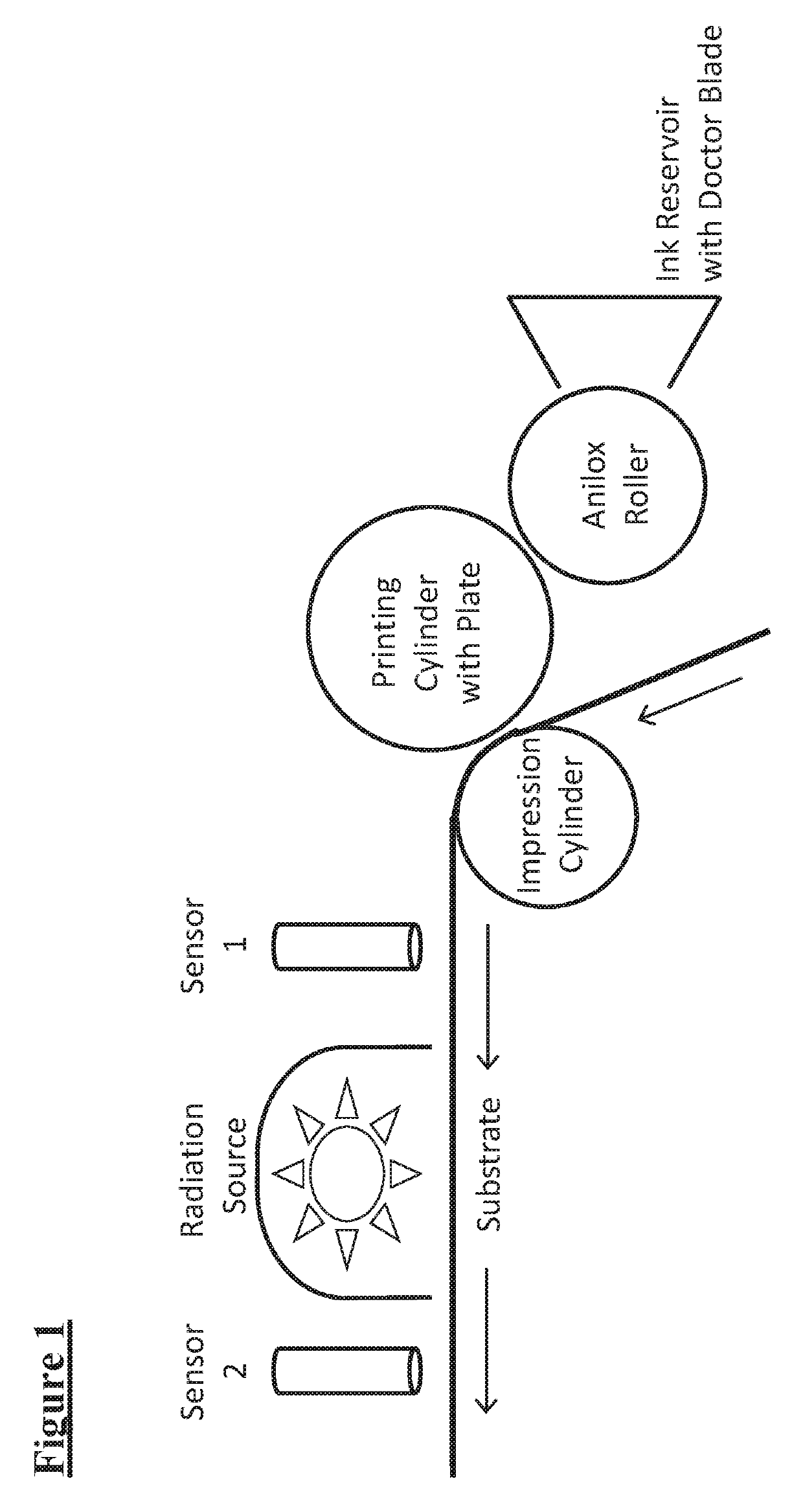
In-line coating weight and radiant energy exposure measurement
a technology of radiant energy and exposure measurement, which is applied in the direction of instruments, inks, fluorescence/phosphorescence, etc., can solve the problems of waste, thousands of feet, and inability to accurately measure the thickness of coating substrates, and the existing methods for measuring coating weight involve tedious, laborious, and inconvenient to opera
- Summary
- Abstract
- Description
- Claims
- Application Information
AI Technical Summary
Benefits of technology
Problems solved by technology
Method used
Image

Examples
example 1
[0081]Step 1: Preparation of Energy Curable Coating Material with Fluorescent Probe
[0082]Probe 1 was added to a UV curable flexographic overprint varnish to produce a printable radiation curable material as shown in Table 1. This coating contains acrylate monomers and oligomers, a Type II photoinitiator, amine synergists, and other additives.
TABLE 1Example 1 Formulation with 6.7 ppm of fluorescent probeMaterialTypeAmount (wt. %)TrimethylolpropaneAcrylate Monomer49.41933triacrylateTriethanolamineSynergist3.00MethyldiethanolamineSynergist3.00Ebecryl 9161Epoxy Acrylate34.00OligomerOmnirad OMBBType II9.00PhotoinitiatorIrgacure 1173Photoinitiator1.00Erbeck OneSlip Agent0.18Foamtrol 110Antifoam0.10UV InhibitorStabilizer0.20Optiblanc PLOptical Brightener0.101Probe 1Fluorescent Probe0.00067Total100.001Probe 1 is chloroaluminum phthalocyanine. Probe 1 was first blended into some finished UV coating product as a concentrate at 500 ppm using a lab mixer. This concentrate was then added to 12 k...
examples 2-5
[0096]Step 1: Preparation of Energy Curable Coating Material with Fluorescent Probe
[0097]Probe 2 was added to an energy curable flexographic overprint varnish to produce printable radiation curable materials as shown in Examples 2, 3, 4, and 5.
TABLE 4Examples 2-5 Formulations with 12 ppm of fluorescent probeAmount (wt. %)MaterialTypeEx. 2Ex. 3Ex. 4Ex. 5Laromer LR 8765Acrylate Resin98.7694.7694.7694.76WaterDiluent0.23880.23880.23880.2388Omnirad BDKType I—4——PhotoinitiatorOmnirad TPO-LType I——4—PhotoinitiatorMichler's EthylType II———4KetonePhotoinitiatorICM 1042Leveling Agent11112Probe 2Fluorescent Probe0.00120.00120.00120.0012Total1001001001002Probe 2 is methylene blue. Probe 2 was first dissolved in water to make a solution 0.5 wt. %. This aqueous dye concentrate was then blended together with other ingredients on a laboratory mixer.
[0098]Example 2 is curable by electron beam exposure but not by UV light exposure, because it contains acrylate resin but no photoinitiator. Examples 3 ...
examples 6 and 7
[0105]Step 1: Preparation of an Electron Beam Curable Coating Material with Fluorescent Probe
[0106]Probe 3 and Probe 2 were each added to energy curable flexographic overprint varnishes to produce printable e-beam curable materials Examples 6 and 7, respectively. Table 6 shows the composition of Example 6. Example 7 has the same composition as that of Example 2 above. Neither example contains a photoinitiator.
TABLE 6Example 6 Formulation with 2.4 ppm of fluorescent probeMaterialTypeAmount (wt. %)Laromer LR 8765Acrylate Resin98.952WaterDiluent0.04776ICM 1042Leveling Agent13Probe 3Fluorescent Probe0.00024Total1003Probe 3 is diethyl carbocyanine. Probe 3 was first dissolved in water to make a solution 0.5 wt. %. This aqueous dye concentrate was then blended together with other ingredients on a laboratory mixer.
Step 2: Preparation of Coatings and UV Light Exposure
[0107]Proofs of each coating were made on white polypropylene label stock. Example 7 was proofed using a 14.8 bcm anilox hand...
PUM
| Property | Measurement | Unit |
|---|---|---|
| wavelength | aaaaa | aaaaa |
| wavelength | aaaaa | aaaaa |
| wavelength | aaaaa | aaaaa |
Abstract
Description
Claims
Application Information