Method of Determining a Characteristic of a Structure, and Metrology Apparatus

a technology of structure and characteristic, applied in the direction of photomechanical apparatus, instruments, material analysis through optical means, etc., can solve the problem of difficult to reproduce the pattern on the substrate, and achieve the effect of reducing the variation of contrast with position

Active Publication Date: 2019-10-10
ASML NETHERLANDS BV
View PDF0 Cites 5 Cited by
  • Summary
  • Abstract
  • Description
  • Claims
  • Application Information

AI Technical Summary

Benefits of technology

[0015]Allowing the difference to be an oblique angle provides freedom for reducing an unwanted variation of contrast with position in the first interference pattern. Reducing a variation of contrast with position facilitates formation of useful features (e.g. fringes) in the first interference pattern.
[0016]In an embodiment, the method comprises adjusting the direction of the first reference radiation onto the sensor relative to the direction of the first illumination radiation onto the structure to reduce a variation of contrast with position in the first interference pattern.
[0017]Performing this adjustment allows unwanted variation of contrast with position in the first interference pattern to be reduced.

Problems solved by technology

In general, the smaller k1 the more difficult it becomes to reproduce the pattern on the substrate that resembles the shape and dimensions planned by a circuit designer in order to achieve particular electrical functionality and performance.

Method used


Image

  • Method of Determining a Characteristic of a Structure, and Metrology Apparatus
  • Method of Determining a Characteristic of a Structure, and Metrology Apparatus
  • Method of Determining a Characteristic of a Structure, and Metrology Apparatus

Examples


Embodiment Construction

[0038]In the present document, the terms “radiation” and “beam” are used to encompass all types of electromagnetic radiation, including ultraviolet radiation (e.g. with a wavelength of 365, 248, 193, 157 or 126 nm) and EUV (extreme ultra-violet radiation, e.g. having a wavelength in the range of about 5-100 nm).

[0039]The term “reticle”, “mask” or “patterning device” as employed in this text may be broadly interpreted as referring to a generic patterning device that can be used to endow an incoming radiation beam with a patterned cross-section, corresponding to a pattern that is to be created in a target portion of the substrate. The term “light valve” can also be used in this context. Besides the classic mask (transmissive or reflective, binary, phase-shifting, hybrid, etc.), examples of other such patterning devices include a programmable mirror array and a programmable LCD array.

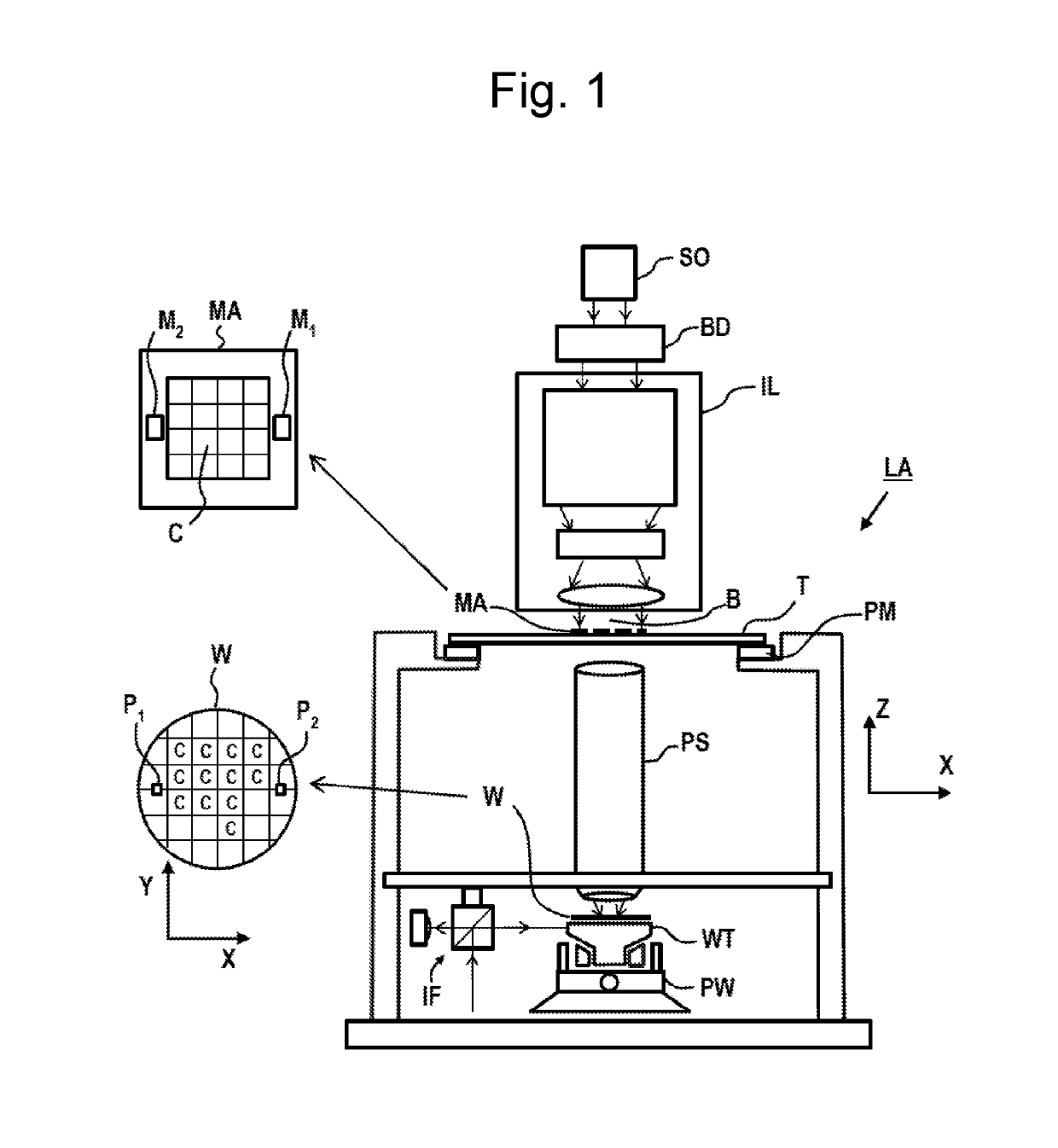
[0040]FIG. 1 schematically depicts a lithographic apparatus LA. The lithographic apparatus LA includes ...


PUM

PropertyMeasurementUnit
azimuthal anglesaaaaaaaaaa

Abstract

Methods and apparatus are disclosed for determining a characteristic of a structure. In one arrangement, the structure is illuminated with first illumination radiation to generate first scattered radiation. A first interference pattern is formed by interference between a portion of the first scattered radiation reaching a sensor and first reference radiation. The structure is also illuminated with second illumination radiation from a different direction. A second interference pattern is formed using second reference radiation. The first and second interference patterns are used to determine the characteristic of the structure. Azimuthal angles of the first and second reference radiations onto the sensor are different.

Description

FIELD[0001]The present invention relates to determining a characteristic of a structure manufactured on a substrate.BACKGROUND[0002]A lithographic apparatus is a machine constructed to apply a desired pattern onto a substrate. A lithographic apparatus can be used, for example, in the manufacture of integrated circuits (ICs). A lithographic apparatus may, for example, project a pattern (also often referred to as “design layout” or “design”) at a patterning device (e.g., a mask) onto a layer of radiation-sensitive material (resist) provided on a substrate (e.g., a wafer).[0003]To project a pattern on a substrate a lithographic apparatus may use electromagnetic radiation. The wavelength of this radiation determines the minimum size of features which can be formed on the substrate. Typical wavelengths currently in use are 365 nm (i-line), 248 nm, 193 nm and 13.5 nm. A lithographic apparatus, which uses extreme ultraviolet (EUV) radiation, having a wavelength within the range 4-20 nm, fo...

Claims


Application Information

Patent Timeline
Patent Type & Authority Applications(United States)
IPC IPC(8): G03F7/20G01N21/88
CPCG03F7/70633G01N21/8806G03F7/70941G03F7/70625
Inventor DE BOER, JOHANNES FITZGERALDTENNER, VASCO TOMASDEN BOEF, ARIE JEFFREYMESSINIS, CHRISTOS
Owner ASML NETHERLANDS BV
Why Eureka
Try Eureka