
Brick/block laying machine incorporated in a vehicle

a technology of brick/block laying machine and vehicle, which is applied in the direction of machine-to-machine/machine-type communication service, total factory control, programme control, etc., can solve the problems of affecting the progress of bricks through the chain, occupying considerable space, and affecting the quality of bricks. , to achieve the effect of improving the quality of bricks, reducing the risk of accidents, and improving the safety of bricks

Active Publication Date: 2019-10-17
FASTBRICK IP PTY LTD
View PDF0 Cites 19 Cited by
  • Summary
  • Abstract
  • Description
  • Claims
  • Application Information

AI Technical Summary

Benefits of technology

The invention is about an automated brick laying machine that can measure and reject damaged or sub-standard bricks, and apply corrections to accurately lay bricks of varying tolerance of shape or dimension. The machine has a first brick machining tool with a clamp to secure the brick and prevent damage during the cutting action. The computerized vision systems and physical measuring probes allow the machine to automatically measure and correct any errors in the bricks. Overall, this invention improves the efficiency and accuracy of the brick laying process.

Problems solved by technology

This meant that the slowest process limited the progress of bricks through the chain.
The chain had brick griping clamps attached to it, so as it wrapped back and forth, it took up considerable space.
It was also determined that some cut bricks could be quite short compared to their height and would be unstable if transported on a flat belt conveyor.
In the case of a telescopic stick and boom, dealing with excess belt length would encounter the same problems as the chain conveyor.

Method used


Image

  • Brick/block laying machine incorporated in a vehicle
  • Brick/block laying machine incorporated in a vehicle
  • Brick/block laying machine incorporated in a vehicle

Examples


Embodiment Construction

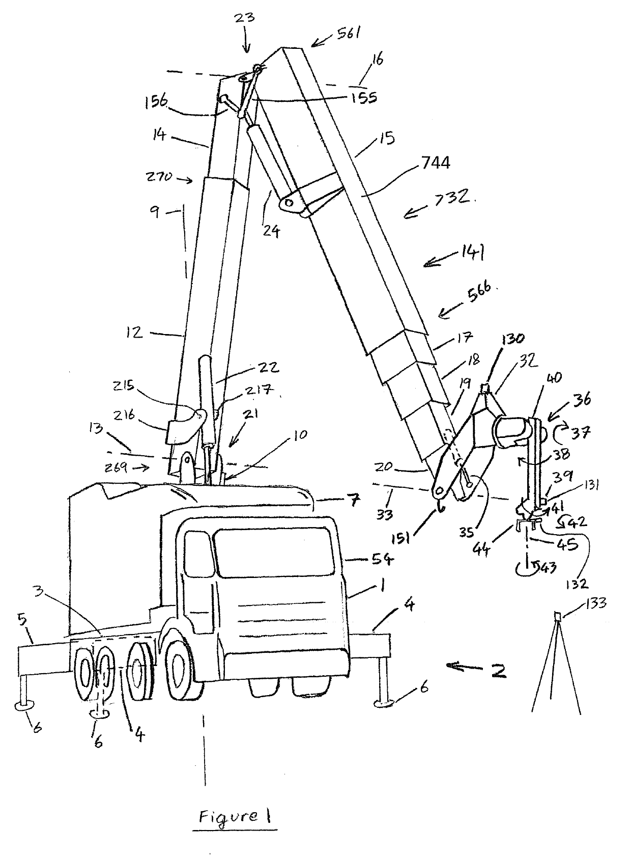
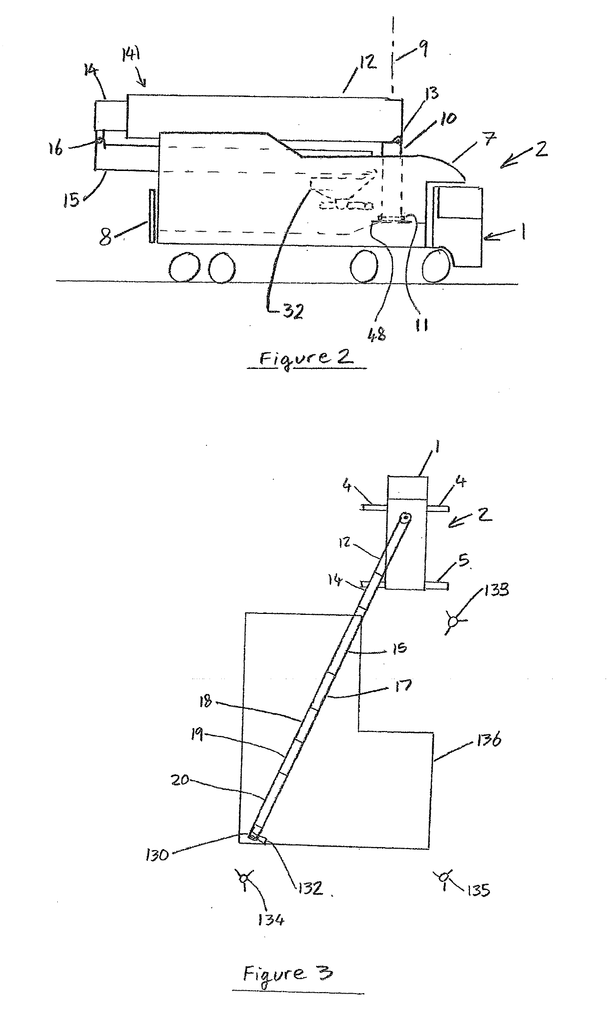
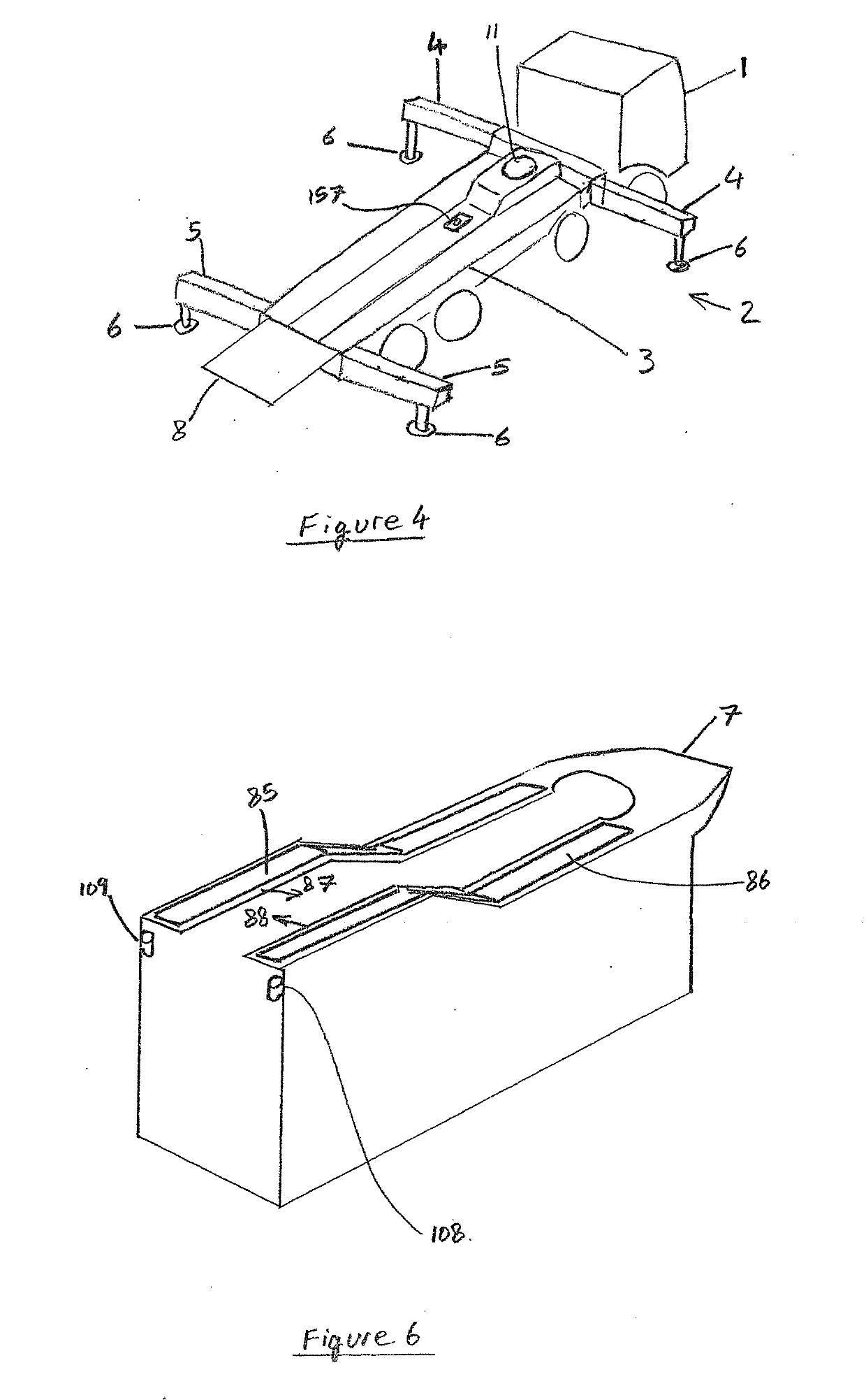
[0174]Referring to FIG. 1, a truck 1 supports a brick laying machine 2 which is mounted on a frame 3 on the chassis (not shown) of the truck. The frame 3 provides additional support for the componentry of the brick laying machine 2 beyond the support that would be provided by a typical truck chassis. Referring also to FIG. 5, the frame 3 supports packs or pallets of bricks 52, 53. De-hacker robots can take rows of bricks off the pallets and place them on a platform 51. A transfer robot can then pick up an individual brick and move it to, or between either a saw 46 or a router 47 or a carousel 48. The carousel is located coaxially with a tower 10, at the base of the tower 10. The carousel 48 transfers the brick via the tower 10 to an articulated (folding about horizontal axis 16) telescoping boom comprising first boom element in the form of telescopic boom 12, 14 and second boom element in the form of telescopic stick 15, 17, 18, 19, 20. Each element 12, 14, 15, 17, 18, 19, 20 of the...


PUM

PropertyMeasurementUnit
angleaaaaaaaaaa
flatnessaaaaaaaaaa
flatnessaaaaaaaaaa

Abstract

A self-contained truck-mounted brick laying machine (2) is described. A truck (1) supports the brick laying machine (2) which is mounted on a frame (3) on the truck chassis. The frame (3) supports packs or pallets of bricks (52, 53) placed on a platform (51). A transfer robot can then pick up an individual brick and move it to, or between either a saw (46) or a router (47) or a carousel (48). The carousel is located coaxially with a tower (10), at the base of the tower (10). The carousel (48) transfers the brick via the tower (10) to an articulated (folding about horizontal axis (16)) telescoping boom comprising first boom element in the form of telescopic boom (12, 14) and second boom element in the form of telescopic stick (15, 17, 18, 19, 20). The bricks are moved along the folding telescoping boom by linearly moving shuttles, to reach a brick laying and adhesive applying head (32). The brick laying and adhesive applying head (32) mounts to element (20) of the stick, about an axis (33) which is disposed horizontally. The poise of the brick laying and adhesive applying head (32) about the axis (33) is adjusted and is set in use so that the base (811) of a clevis (813) of the robotic arm (36) mounts about a horizontal axis, and the tracker component (130) is disposed uppermost on the brick laying and 110,111 adhesive applying head (32). The brick laying and adhesive applying head (32) applies adhesive to the brick and has a robot that lays the brick. Vision and laser scanning and tracking systems are provided to allow the measurement of as-built slabs, bricks, the monitoring and adjustment of the process and the monitoring of safety zones. The first, or any course of bricks can have the bricks pre machined by the router module (47) so that the top of the course is level once laid.

Description

TECHNICAL FIELD[0001]This invention belongs to the field of building construction, and relates to a pick and place machine to build a building from bricks or blocks.BACKGROUND ART[0002]The following discussion of the background art is intended to facilitate an understanding of the present invention only. It should be appreciated that the discussion is not an acknowledgement or admission that any of the material referred to was part of the common general knowledge as at the priority date of the application.[0003]The inventor previously described a brick laying machine in U.S. Pat. No. 8,166,727. In practice, as described, this required a large road-going machine to implement.[0004]An early prototype brick laying machine, based on that described in U.S. Pat. No. 8,166,727, and built by the inventor, used a chain conveyor with brick holding clamps attached to the chain. This chain moved from the base of the machine, out along a boom, to the laying head system. There was a small chain t...

Claims


Application Information

Patent Timeline
Patent Type & Authority Applications(United States)
IPC IPC(8): E04G21/22B25J9/16B28D1/00B28D7/04B28D1/18B28D1/10B28D7/00G05B19/4097
CPCB28D1/10G05B2219/35207B25J9/1638B28D1/003B60P3/28B28D1/186G05B19/4097G01C15/002E04G21/22B28D7/005B28D7/04B25J9/1635G05B2219/45086G01S17/66G05B2219/40257G06F2111/20G06F30/13B25J9/162Y02B10/30G05B2219/40513G05B2219/40298B25J9/1664G05B2219/39172G05B19/4182G05B19/41815G06F16/1734Y02P90/02H04W4/70G06F16/00B25J5/00B25J9/1612B25J9/1651B25J19/021B60P1/48E04F21/023G05B2219/39001B25J9/161B25J9/1684B25J9/1694B25J13/089B25J19/022B25J9/023B25J9/1633B25J9/1674E04B1/02B66C13/22B25J9/1679B25J9/1697E04B2/04G05B19/416
Inventor PIVAC, MARK
Owner FASTBRICK IP PTY LTD
Learn More