Electrochemical hydrogen pump and method for operating electrochemical hydrogen pump

Active Publication Date: 2019-10-17
PANASONIC INTELLECTUAL PROPERTY MANAGEMENT CO LTD
View PDF0 Cites 3 Cited by
  • Summary
  • Abstract
  • Description
  • Claims
  • Application Information

AI Technical Summary

Benefits of technology

[0008]Since hydrogen energy has been desirably used with high efficiency, it is important to i

Problems solved by technology

However, the improvement in the efficiency of a hydrogen compression operation from the viewp

Method used


Image

  • Electrochemical hydrogen pump and method for operating electrochemical hydrogen pump
  • Electrochemical hydrogen pump and method for operating electrochemical hydrogen pump
  • Electrochemical hydrogen pump and method for operating electrochemical hydrogen pump

Examples


embodiment

Structure of Electrochemical Hydrogen Pump

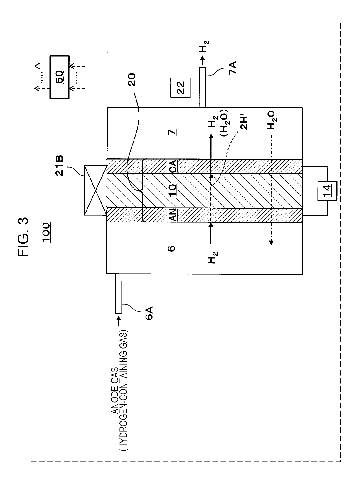
[0066]FIG. 3 illustrates an example of an electrochemical hydrogen pump according to an embodiment.

[0067]In the example illustrated in FIG. 3, an electrochemical hydrogen pump 100 includes a cell (MEA) 20, a voltage applier 14, a cooler 21B, a pressure gage 22, and a controller 50. The cell 20 includes a proton conductive electrolyte membrane 10, an anode AN, and a cathode CA.

[0068]In the electrochemical hydrogen pump 100 according to this embodiment, the cell 20 is disposed so as to partition the space in a container. The region of the container on the anode AN side constitutes an anode chamber 6 into which an anode gas flows, and the region of the container on the cathode CA side constitutes a cathode chamber 7 from which a hydrogen gas containing water vapor (hereafter referred to as hydrogen) flows out.

[0069]An example of the anode gas is a hydrogen-containing gas. That is, protons are generated from hydrogen in the hydrogen-containing g...

first example

[0131]FIG. 6 illustrates an example of an electrochemical hydrogen pump in a first example according to an embodiment.

[0132]In the example illustrated in FIG. 6, an electrochemical hydrogen pump 100 includes a cell (MEA) 20, a voltage applier 14, a heater 21A, a pressure gage 22, and a controller 50.

[0133]The cell 20, the voltage applier 14, and the pressure gage 22 are the same as those in the above embodiment and thus the descriptions thereof are omitted.

[0134]The heater 21A is a unit for heating the cell 20. The heater 21A may have any configuration as long as the cell 20 can be heated. The heater 21A may be, for example, an electric heater that heats the electrochemical hydrogen pump 100 from its periphery. When the electrochemical hydrogen pump 100 includes a stacked body obtained by alternately stacking cells 20 and separators, the heater 21A may be a heating unit that heats the cells 20 by circulating hot water through the stacked body. That is, in this case, a water flow pat...

second example

[0138]An electrochemical hydrogen pump and a method for operating the electrochemical hydrogen pump according to this example are the same as those in the first example (FIG. 6), except for the control mechanism below of the heater 21A with the controller 50.

[0139]Before the voltage applier 14 applies a voltage between the anode AN and the cathode CA, the controller 50 starts a heating operation of the heater 21A to increase the temperature of the cell 20. That is, before the voltage applier 14 applies a voltage between the anode AN and the cathode CA, a step of starting a heating operation of the heater 21A to increase the temperature of the cell 20 is performed.

[0140]A differential pressure between the anode AN and the cathode CA is not generated before the voltage applier 14 applies a voltage between the anode AN and the cathode CA. In this case, the back diffusion of water through the proton conductive electrolyte membrane 10 is less likely to occur. Thus, even if the temperatur...


PUM


Abstract

An electrochemical hydrogen pump includes: a cell including a proton conductive electrolyte membrane having a first main surface and a second main surface, a cathode disposed on the first main surface of the proton conductive electrolyte membrane, and an anode disposed on the second main surface of the proton conductive electrolyte membrane; a voltage applier that applies a voltage between the anode and the cathode; a cooler that cools the cell; and a controller that controls the cooler to increase an amount of cooling per unit time of the cell when a pressure of a cathode gas flow path on the cathode increases.

Description

BACKGROUND1. Technical Field[0001]The present disclosure relates to an electrochemical hydrogen pump and a method for operating the electrochemical hydrogen pump.2. Description of the Related Art[0002]In recent years, hydrogen has received attention as a clean alternative energy source in place of fossil fuel from the viewpoint of environmental problems such as global warming and energy problems such as depletion of petroleum resources. Hydrogen is promising for clean energy because, in principle, only water is released as a result of combustion of hydrogen, and carbon dioxide that is a cause of global warming is not released and nitrogen oxides are substantially not released. For example, fuel cells are used as devices that use hydrogen as a fuel with high efficiency. Such fuel cells have been developed and put into widespread use for power supplies for automobiles and independent power generation for household use.[0003]In the forthcoming hydrogen society, the technical developmen...

Claims


Application Information

Patent Timeline
IPC IPC(8): F04F9/02C25B9/23
CPCF04F9/02C25B9/00C25B15/02C25B1/04C25B9/73C25B1/02C25B15/021C25B15/025B01D53/326
Inventor ZHANG, JINWAKITA, HIDENOBUOKAICHI, ATSUO
Owner PANASONIC INTELLECTUAL PROPERTY MANAGEMENT CO LTD
Why Eureka
Try Eureka