
Textile fiber drying

a textile fiber and textile technology, applied in drying machines, lighting and heating apparatus, furnaces, etc., can solve the problems of insufficient loosening of fibers, impaired drying capacity, and compressed fibers between belts,

Active Publication Date: 2019-10-17
AUTEFA SOLUTIONS GERMANY GMBH
View PDF0 Cites 4 Cited by
  • Summary
  • Abstract
  • Description
  • Claims
  • Application Information

AI Technical Summary

Benefits of technology

The present invention provides an improved technology for drying wet or damp fibers, especially viscose fibers, by avoiding fiber compression and increasing the effective surface area of the fibers available for drying while reducing the volume density of the fiber mat. The drying process is enhanced by the inclusion of fly, and a continuous return of the separated fibers to the dry fiber mat is possible. The invention also allows for a reduced length of the drying section and a continuous drying process due to the movement of both the treatment belt and the filter belt. The invention also avoids compression between the treatment belt and the filter belt by using an upwardly directed air stream and a middle chamber defined between the treatment belt and the filter belt. The fiber mat can expand freely in the vertical direction during the drying process as a result of the distance between the treatment belt and the filter belt. The invention also includes a high percentage of the fibers separated as fly from the drying process and ensures an air-tight encapsulation of the (middle) chamber.

Problems solved by technology

However, the downwardly directed air stream leads to various drawbacks.
The effective surface of the fibers that can be utilized for the drying decreases due to the compaction, so that the drying capacity is impaired.
Inhomogeneous distributions of zones with high and low permeability to air may also develop, which is likewise disadvantageous for the result of the drying.
The fibers are compressed between the belts and are not consequently loosened sufficiently.
The fibers are likewise not dried optimally as a result.

Method used


Image

  • Textile fiber drying
  • Textile fiber drying
  • Textile fiber drying

Examples


Embodiment Construction

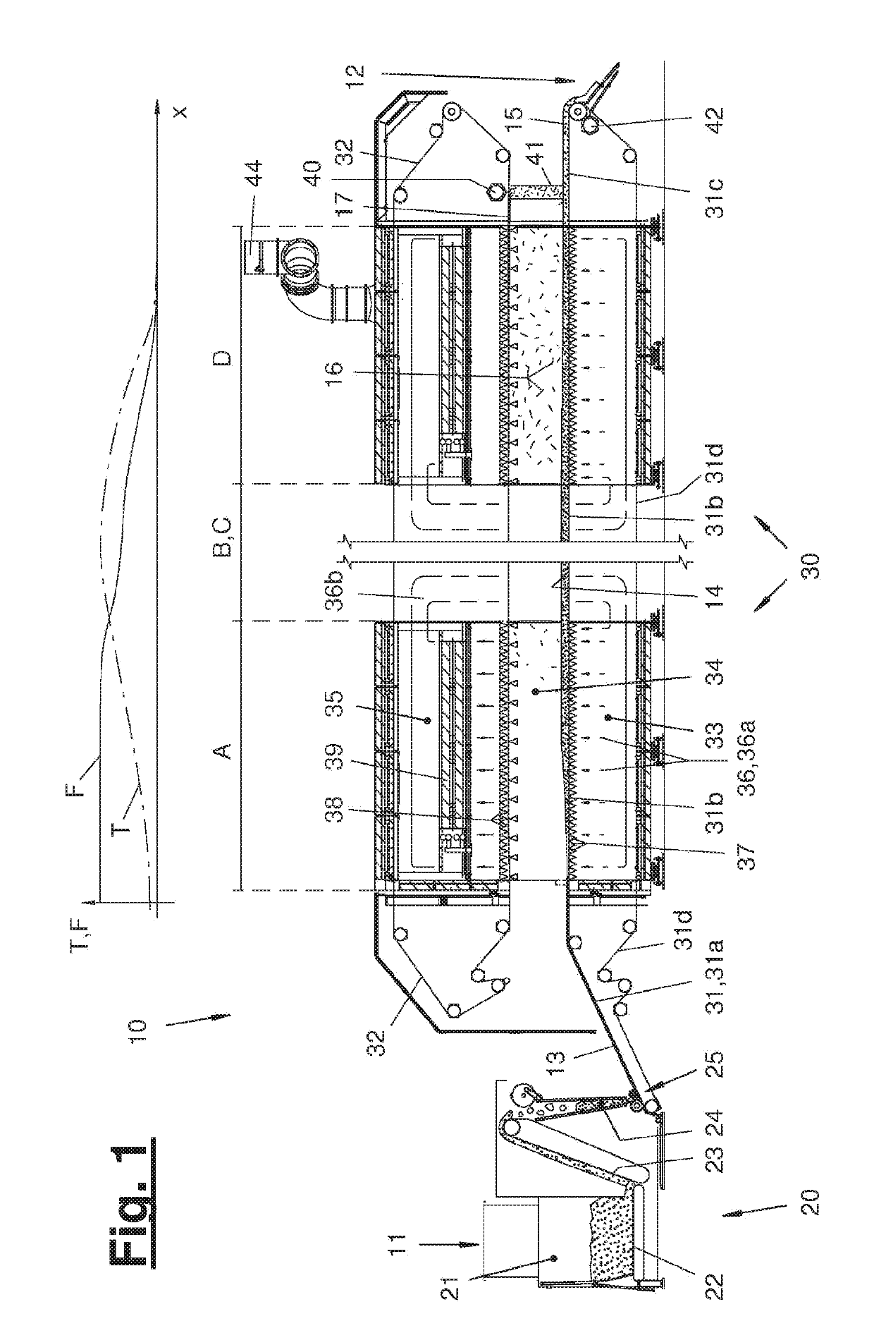
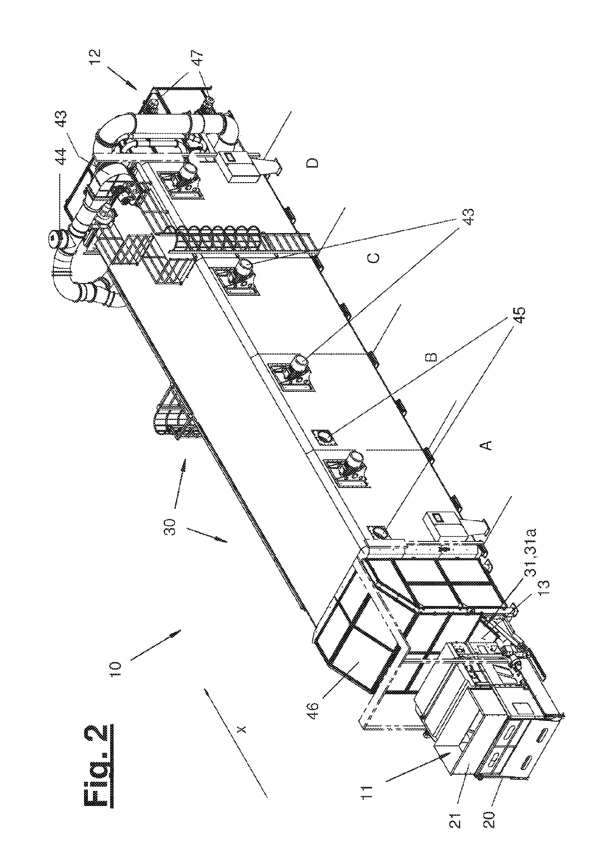
[0029]Referring to the drawings, FIG. 1 shows a fiber treatment plant (10) with a fiber mat producer (20) and with a fiber dryer (30). A conveying direction (x) extends through the fiber treatment plant (10) from the left side to the right side in FIG. 1.

[0030]In the area of a wet fiber feed hopper (11), wet or damp fibers can be fed to the fiber treatment plant (10) in any desired initial form, for example, as bulk material, which can be filled into the feed tub of the fiber mat producer (20). The fiber mat producer (20) shown in FIG. 1 is an exemplary embodiment in the manner of a hopper feeder. As an alternative, any other desired fiber mat producer (20) may be provided, for example, in the form of a feed shaft or of a vibrating shaft feeder. Likewise as an alternative, the fiber treatment plant (10) may be formed without a fiber mat producer (20), for example, if the wet or damp fibers can already be fed as a fiber mat or fiber strand from a working device arranged upstream.

[003...


PUM


Abstract

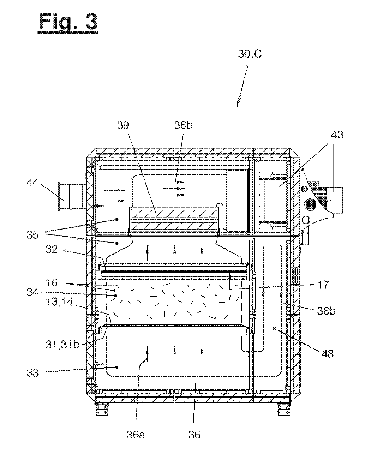
A method and a fiber-treatment system dry wet or damp fibers. A fiber mat (13) including wet or damp fibers is formed on a treatment band (31) which is moved in a conveying direction (x). An air flow (36, 36a) composed of heated drying air is generated in the fiber dryer (30). The heated drying air is guided in an upward direction through the treatment band and the fibers contained in the fibre mat (13, 14) are loosened and dried. Linters (16) possibly produced by any moving fibers are captured by a filter band (32) arranged above the treatment band, which is also moved in the conveying direction (x). At the outlet of the fiber dryer, the fibers are detached from a support (17) formed on the filter band, in particular when guiding the detached fibers back towards the dried fibers guided to the treatment band (31, 31c).

Description

CROSS REFERENCE TO RELATED APPLICATIONS[0001]This application is a United States National Phase Application of International Application PCT / EP2017 / 080807 filed Nov. 29, 2017, and claims the benefit of priority under 35 U.S.C. § 119 of German Application 10 2016 122 965.2, filed Nov. 29, 2016, the entire contents of which are incorporated herein by reference.TECHNICAL FIELD[0002]The present invention pertains to a technique for drying damp or wet textile fibers. The present disclosure is directed especially towards a fiber treatment plant for drying damp or wet viscose fibers.TECHNICAL BACKGROUND[0003]Viscose fibers impose special requirements on a drying process because they tend to undergo compaction and mutual adhesion in the wet state, on the one hand, and because they tend to generate fly (also known as fiber fly or airborne fiber) in the half-dry or dry state, on the other hand.[0004]The “drying of fibers” is defined within the framework of the present disclosure as the drying...

Claims


Application Information

Patent Timeline
Patent Type & Authority Applications(United States)
IPC IPC(8): F26B3/08F26B17/02F26B17/04F26B21/08F26B21/10
CPCF26B17/04F26B21/08F26B3/08F26B17/026F26B21/10
Inventor NIKLAUS, MICHAEL
Owner AUTEFA SOLUTIONS GERMANY GMBH
Learn More