
Customizable orthotic/prosthetic braces and lightweight modular exoskeleton

a technology of orthotic/prosthetic braces and exoskeletons, which is applied in the field of customizable orthotic/prosthetic braces and lightweight modular exoskeletons, can solve the problems of localized failure points, increased cost, and limited options for location and geometry of the structure, so as to improve the strength and rigidity of such braces, and is easily moldable

Active Publication Date: 2019-10-31
UNIV HOUSTON SYST
View PDF0 Cites 16 Cited by
  • Summary
  • Abstract
  • Description
  • Claims
  • Application Information

AI Technical Summary

Benefits of technology

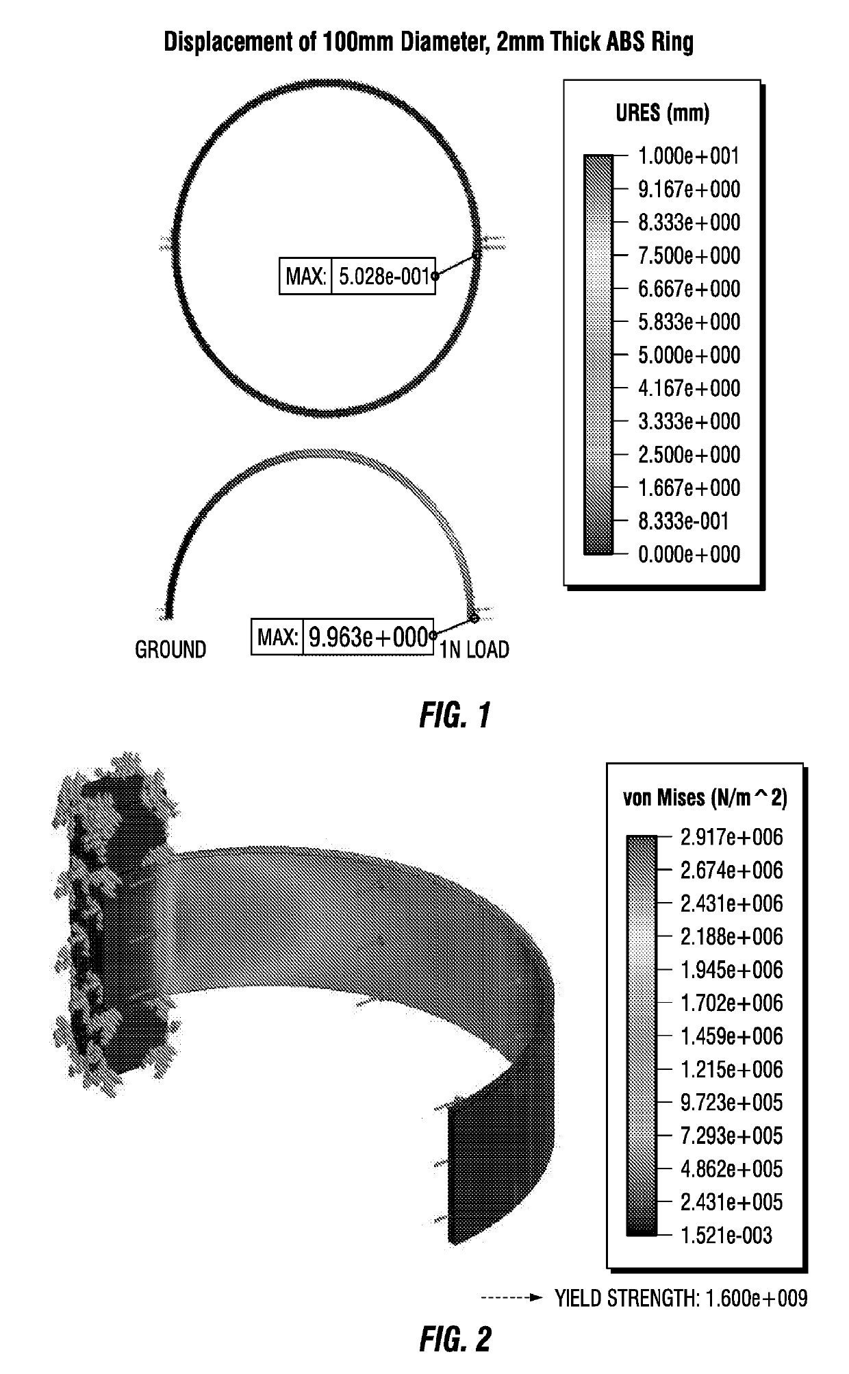
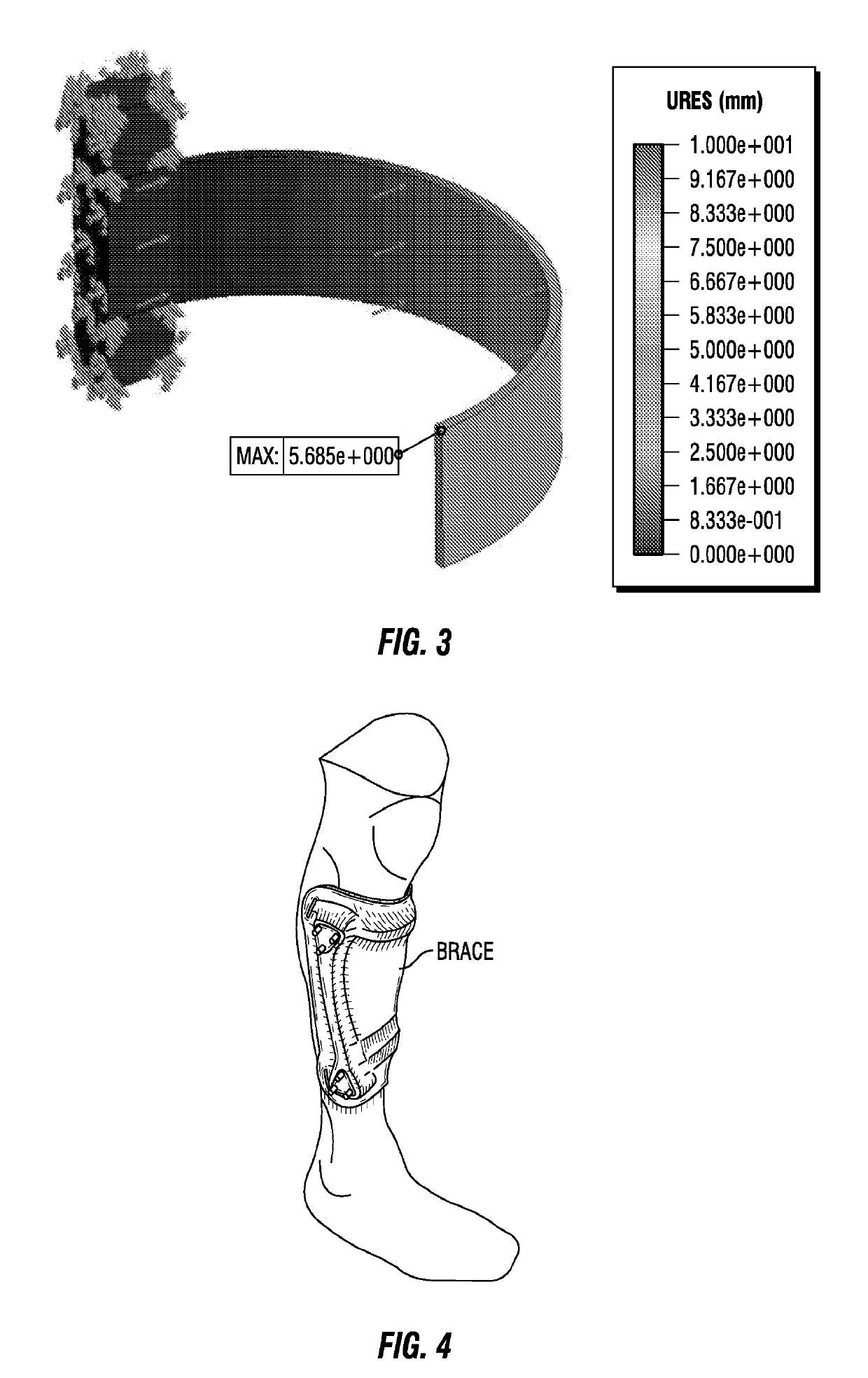
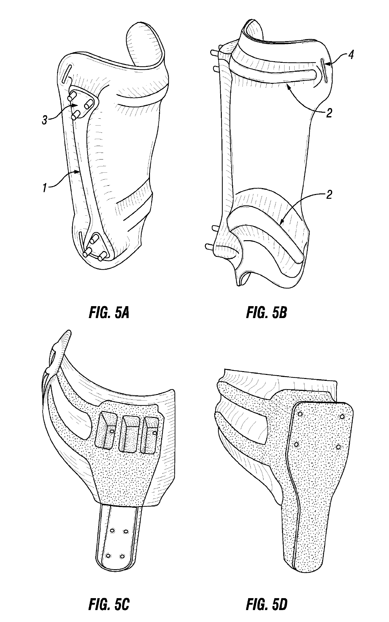
The invention is about improving customizable orthotic / prosthetic braces and a lightweight modular exoskeleton for individuals with lower limb motor impairment. This improvement makes the braces stronger and stiffer without adding weight. The braces have a structural frame embedded between an inner shell and outer shell, which are made of easily moldable materials that can conform to the user's limb.

Problems solved by technology

These current orthopedic brace manufacturing methods are largely dependent on hand methods that are prone to geometric errors requiring many iterations to make a usable form.
Additionally the interface between the structural component of the orthosis and the user interface brace often requires mechanical fasteners which increase size and weight and concentrate stresses on the plastic or composite braces causing localized failure points.
Just attaching metal hardware to braces for the structural support greatly limits the options for location and geometry of the structure or dramatically increases cost.
Loss or impairment of motor function can take a negative toll on individuals causing physical, mental and monetary hardships.
Decreased mobility has been linked to higher blood pressure, shorter life expectancy, social stigma and increased rates of depression.

Method used


Image

  • Customizable orthotic/prosthetic braces and lightweight modular exoskeleton
  • Customizable orthotic/prosthetic braces and lightweight modular exoskeleton
  • Customizable orthotic/prosthetic braces and lightweight modular exoskeleton

Examples


Embodiment Construction

[0044]Refer now to the drawings wherein depicted elements are not necessarily shown to scale and wherein like or similar elements are designated by the same reference numeral through the several views.

[0045]Referring to the drawings in general, it will be understood that the illustrations are for the purpose of describing particular implementations of the disclosure and are not intended to be limiting thereto. While most of the terms used herein will be recognizable to those of ordinary skill in the art, it should be understood that when not explicitly defined, terms should be interpreted as adopting a meaning presently accepted by those of ordinary skill in the art.

[0046]It is to be understood that both the foregoing general description and the following detailed description are exemplary and explanatory only, and are not restrictive of the invention, as claimed. In this application, the use of the singular includes the plural, the word “a” or “an” means “at least one”, and the use...


PUM


Abstract

Improved customizable orthotic / prosthetic braces and a lightweight modular exoskeleton may aid individuals with lower limb motor impairment, including children. These customizable orthotic / prosthetic braces improve the strength and rigidity of such braces without a weight penalty. A structural frame is embedded between an inner shell and outer shell, which comprise materials that are easily moldable to conform to a user's limb. The lightweight modular exoskeleton system provides six (6) joint actuators, which are designed to be modular, that act as the active joints (e.g. hips, knees, and ankles) of the exoskeleton. Additionally, the exoskeleton may also provide four (4) passive joints for inversion / eversion of the legs and feet. Foot, crutch, and hip assemblies may also be provided IN for the exoskeleton. Further, the six joint actuators may be utilized between the hip brace assembly and thigh brace assembly, the thigh and shank brace assembly, and the shank brace assembly and foot assembly, where the braces may correspond to the customizable orthotic / prosthetic design. The modularity of the actuators and braces allows for exoskeleton assemblies that can be tailored to patient specific needs.

Description

RELATED APPLICATIONS[0001]This application claims the benefit of U.S. Provisional Patent Application No. 62 / 349,921 filed on Jun. 14, 2016, which is incorporated herein by reference.FIELD OF THE INVENTION[0002]This invention relates to a customizable orthotic / prosthetic braces and lightweight modular exoskeleton.BACKGROUND OF INVENTION[0003]Almost a million people in the US alone use a lower limb orthosis. Orthosis devices range in function and application, but a couple features are the same through all systems—an orthosis must interface with the user in a comfortable and safe manner and the orthosis must provide some support to the user. These vary from custom foot insoles to full leg frames attached to patients with customized braces. Systems with rigid frames across joints often interface with the user through a custom formed brace that matches the geometry of the individual's leg.[0004]Current technology takes advantage of a few different methods for constructing these custom br...

Claims


Application Information

Patent Timeline
Patent Type & Authority Applications(United States)
IPC IPC(8): A61H3/00A61F5/01A61H1/02A61H3/02
CPCA61H3/02A61H2201/1642A61H3/00A61H2201/165A61H2201/1215A61H2201/5082A61H2201/5066A61F5/0123A61H2003/007A61H1/0262A61H2201/5079A61H2201/5061A61H1/024A61H1/0244A61H1/0266A61H2201/5058A61H2201/5069
Inventor CONTRERAS-VIDAL, JOSE LUISGORGES, JEFFREY JOSEPHKILICARSLAN, ATILLA
Owner UNIV HOUSTON SYST
Learn More