Part comprising a substrate and an environmental barrier

a technology of environmental barrier and substrate, which is applied in the direction of engine components, mechanical equipment, machines/engines, etc., can solve the problem that the barrier effect against oxidizing species may nevertheless be negatively affected

Active Publication Date: 2019-10-31
SAFRAN CERAMICS SA +2
View PDF0 Cites 4 Cited by
  • Summary
  • Abstract
  • Description
  • Claims
  • Application Information

AI Technical Summary

Benefits of technology

[0049]FIG. 5 shows a test result comparing the barrier effect against diffusion of oxidizing species presented by first layers suitable for use in the context of the invention and by an environmental barrier layer of the prior art; and

Problems solved by technology

The barrier effect against oxidizing species may nevertheless be negatively affected if the molar content of oxide REb2O3 in the first layer is too high, which is why this content of REb2O3 is limited to at most 30% in molar percentage.

Method used


Image

  • Part comprising a substrate and an environmental barrier
  • Part comprising a substrate and an environmental barrier

Examples


example

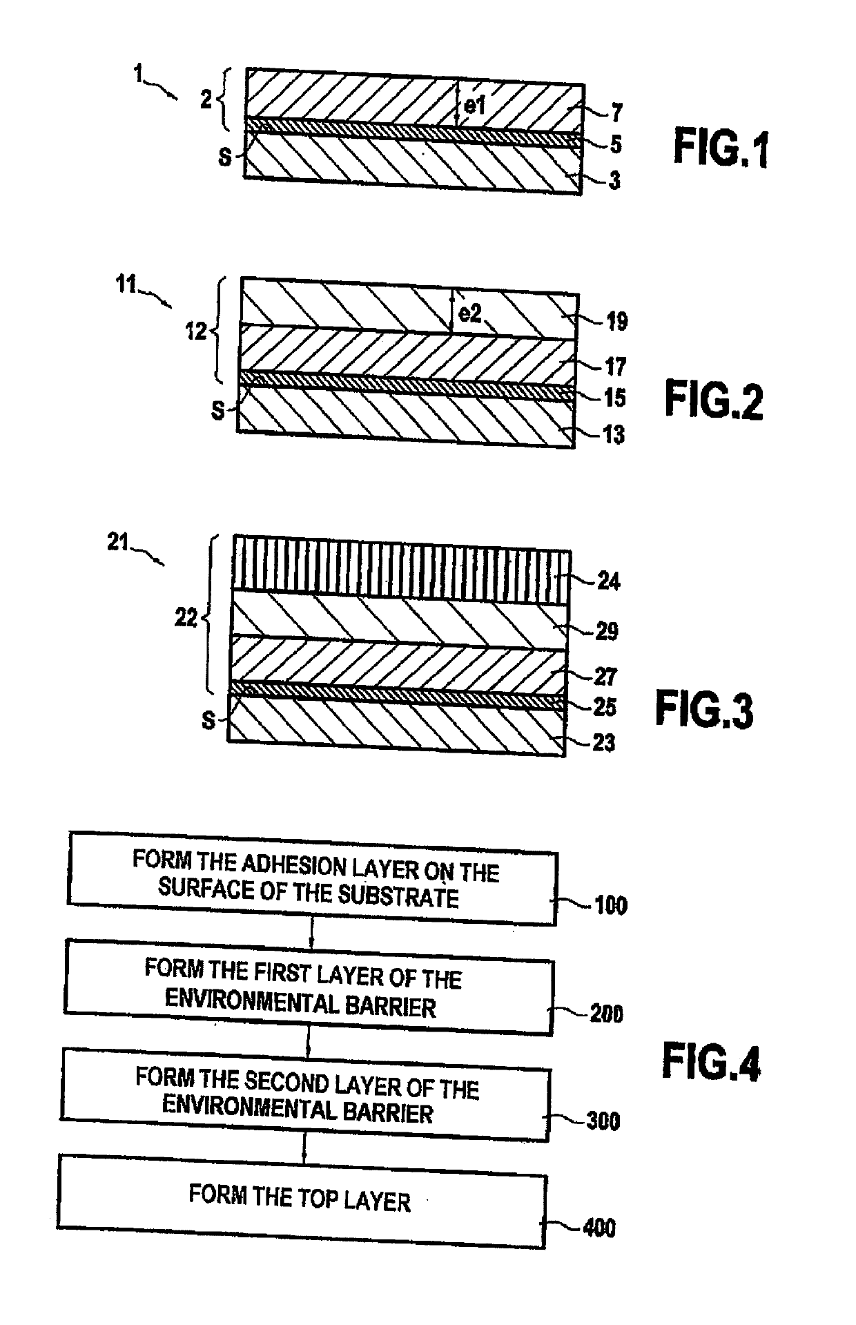
[0087]Three examples of first layers of the invention have been fabricated. The three first layers that were fabricated had the following compositions:

[0088]yttrium disilicate at 95% molar and erbium oxide Er2O3 at 5% molar, this layer being written “DSY+5 at % Er2O3”;

[0089]yttrium disilicate at 90% molar and erbium oxide Er2O3 at 10% molar, this layer being written “DSY+10 at % Er2O3”; and

[0090]yttrium disilicate at 85% molar and erbium oxide Er2O3 at 15% molar, this layer being written “DSY+15 at % Er2O3”.

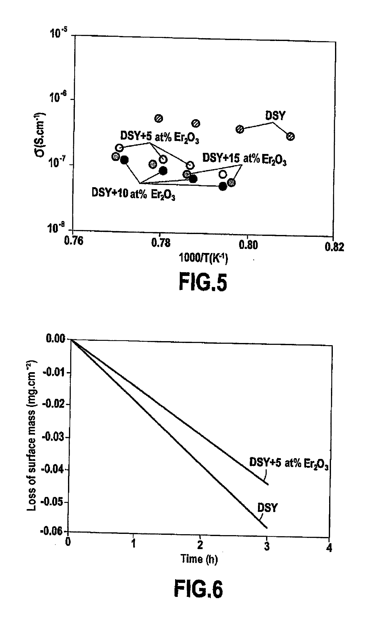
[0091]A prior art environmental barrier layer constituted by yttrium disilicate was fabricated. This layer is written “DSY”.

[0092]FIG. 5 shows a test result comparing the barrier effect against oxidizing species as conferred by each of the three first layers with the barrier effect against the same species as conferred by the DSY layer. FIG. 5 shows that the conductivity to oxidizing species in each of the first layers is significantly less than the conductivity to those same spe...


PUM

PropertyMeasurementUnit
temperatureaaaaaaaaaa
thickness e1aaaaaaaaaa
thicknessaaaaaaaaaa

Abstract

A part includes a substrate, having, adjacent to a surface of the substrate, at least a portion that is made from a material that contains silicon, and an environmental barrier formed on the surface of the substrate, the environmental barrier including at least a first layer including a rare earth disilicate of formula REa2Si2O7 present at a molar content lying in the range 70% to 99.9%, where REa is a rare earth element; and at least one rare earth oxide of formula REb2O3 present at a molar content lying in the range 0.1% to 30%, where REb is a rare earth element different from REa.

Description

BACKGROUND OF THE INVENTION[0001]The invention relates to protecting a substrate in which at least a portion adjacent to a surface of the substrate is made of a material containing silicon, and while the substrate is in use at high temperature in an oxidizing medium, by forming an environmental barrier on the surface of the substrate.[0002]A particular field of application is that of protecting parts made of ceramic matrix composite (CMC) material that form hot parts in gas turbines, such as combustion chamber walls, or turbine rings, turbine nozzles, or turbine blades or vanes, for aeroengines or for industrial turbines.[0003]For such gas turbines, the need to improve efficiency and reduce polluting emissions leads to envisaging the use of ever higher temperatures in the combustion chambers.[0004]Proposals have therefore been made to replace metal materials by CMC materials, in particular for the walls of combustion chambers or for turbine rings. Specifically, CMC materials are kno...

Claims


Application Information

Patent Timeline
Patent Type & Authority Applications(United States)
IPC IPC(8): C04B41/87C04B41/89C04B41/00C04B41/50F01D5/28
CPCC04B41/5024C04B41/87F01D5/284C04B41/89C04B41/0009C04B41/009C04B41/52F01D5/288C04B35/806C04B35/565C04B35/584C04B41/4527C04B41/5045C04B2103/0021C04B41/526
Inventor PIN, LISAARNAL, SIMONREBILLAT, FRANCISMAUVY, FABRICE
Owner SAFRAN CERAMICS SA
Why Eureka
Try Eureka